
Laser radar light source and its repetition frequency switching method

A laser radar and repetition rate technology, applied in the direction of semiconductor laser optical devices, lasers, semiconductor lasers, etc., can solve the problems of laser radar interference, initial pulse energy drop, and inability to achieve accurate detection, etc., to ensure that the pulse energy remains unchanged Effect

Active Publication Date: 2022-05-20
福建海创光电技术股份有限公司
View PDF9 Cites 0 Cited by
  • Summary
  • Abstract
  • Description
  • Claims
  • Application Information

AI Technical Summary

Problems solved by technology

[0002] At present, for ordinary vehicle-mounted laser radars, only laser pulses with the same repetition rate are emitted for target detection. This type of vehicle-mounted laser radar with a single repetition rate is suitable for a single vehicle condition. When the repetition frequency of the lasers emitted by the vehicles is the same, the laser radars between the vehicles will interfere with each other, thus failing to achieve the purpose of accurate detection
[0003] At present, there is a way to adjust the repetition frequency of the pulses emitted by the pulse light source of the vehicle-mounted lidar, that is, to emit pulse trains with different repetition frequencies in different time periods, so as to avoid interference with other vehicles, but this method requires When the repetition frequency is switched, to ensure that the pulse energy of different repetition frequency pulses remains unchanged, then it is necessary to change the pump light power of the pump light source when the pulse repetition frequency is switched. However, the erbium in the pump light emitted by the pump light source The ion lifetime is on the order of milliseconds, so the time to adjust the pulse energy emitted by the laser radar light source by changing the pump will also be on the order of milliseconds, but the switching time of pulse trains with different repetition frequencies is on the order of microseconds, which means After the pulse light source switches the repetition frequency, the pump light source has not yet completed the change of the pump light power, which leads to a decrease in the initial pulse energy output after the pulse light source switches the repetition frequency, resulting in a decrease in detection performance

Method used


Image

  • Laser radar light source and its repetition frequency switching method
  • Laser radar light source and its repetition frequency switching method
  • Laser radar light source and its repetition frequency switching method

Examples


Embodiment Construction

[0049] The principle and spirit of the present invention will be described below with reference to several exemplary embodiments. It should be understood that these embodiments are given only to enable those skilled in the art to better understand and implement the present invention, rather than to limit the scope of the present invention in any way. Rather, these embodiments are provided so that this disclosure will be thorough and complete, and will fully convey the scope of the disclosure to those skilled in the art.

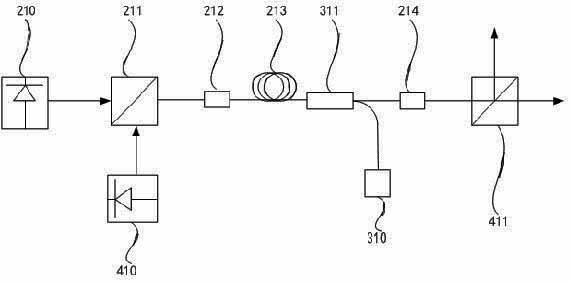
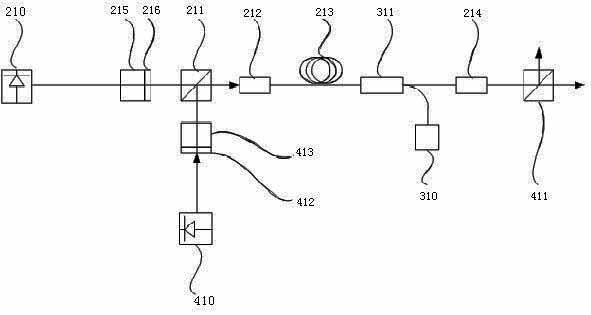
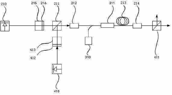
[0050] According to an embodiment of the present invention, a laser radar light source and a repetition frequency switching method thereof are proposed.

[0051] Herein, it should be understood that any number of elements in the drawings is for illustration rather than limitation, and any naming is only for distinction and has no limiting meaning.

[0052] The principle and spirit of the present invention will be explained in detail below with reference to s...


PUM


Abstract

The invention discloses a laser radar light source and a repetition frequency switching method thereof. The laser radar light source comprises: a pulse signal transmitting system for transmitting pulse signal light with different repetition frequencies; a pumping system for amplifying the pulse signal emitted by the pulse signal transmitting system pulse signal light to generate amplified pulse signal light; the control signal emission system is used to emit control signal light to consume part of the pump light power of the pump system; the central control system is connected with the pulse signal emission system, pump The system and the control signal emitting system are electrically connected, and are used to control the pulse signal light to switch between pulse signal lights with different repetition frequencies; control the pumping system to emit pump light; and control the control signal emitting system to emit control signal light. When the repetition frequency is switched, the present invention utilizes the cooperation of the control signal system and the pumping system to ensure that the pump light power always matches the repetition frequency of the pulse signal light, and realizes that the pulse energy remains unchanged when the repetition frequency is switched.

Description

technical field [0001] The invention relates to the field of laser radar, in particular to a laser radar light source and a repetition frequency switching method thereof. Background technique [0002] At present, for ordinary vehicle-mounted laser radars, only laser pulses with the same repetition rate are emitted for target detection. This type of vehicle-mounted laser radar with a single repetition rate is suitable for a single vehicle condition. When the repetition frequency of the lasers emitted by the vehicles is the same, the laser radars between the vehicles will interfere with each other, thus failing to achieve the purpose of accurate detection. [0003] At present, there is a way to adjust the repetition frequency of the pulses emitted by the pulse light source of the vehicle-mounted lidar, that is, to emit pulse trains with different repetition frequencies in different time periods, so as to avoid interference with other vehicles, but this method requires When th...

Claims


Application Information

Patent Timeline
Patent Type & Authority Patents(China)
IPC IPC(8): G01S7/484G01S7/486G01S17/931H01S5/00H01S5/06
CPCG01S7/484G01S7/486G01S17/931H01S5/0071H01S5/005H01S5/0607H01S5/0608H01S5/06
Inventor 张党卫丁广雷张哨峰凌吉武于农村
Owner 福建海创光电技术股份有限公司
Learn More