Auxiliary equipment for medical examination and use method thereof

A technology of auxiliary equipment and horizontal plate, applied in the field of medical inspection, can solve the problems of reducing the efficiency of CT inspection, and achieve the effect of ensuring effectiveness and fluency, overcoming hysteresis, and improving the quality of fixation

Inactive Publication Date: 2022-04-01
王金秀
View PDF1 Cites 0 Cited by
  • Summary
  • Abstract
  • Description
  • Claims
  • Application Information

AI Technical Summary

Problems solved by technology

[0004] Although the overall device achieves the effect of fixing the patient's head, the overall structure is simple, and it still relies on manual operation for auxiliary fixation, which leads to a decrease in the efficiency of CT examination. Therefore, there is an urgent need for an auxiliary device for medical examination and its use method

Method used


Image

  • Auxiliary equipment for medical examination and use method thereof
  • Auxiliary equipment for medical examination and use method thereof
  • Auxiliary equipment for medical examination and use method thereof

Examples


Embodiment 1

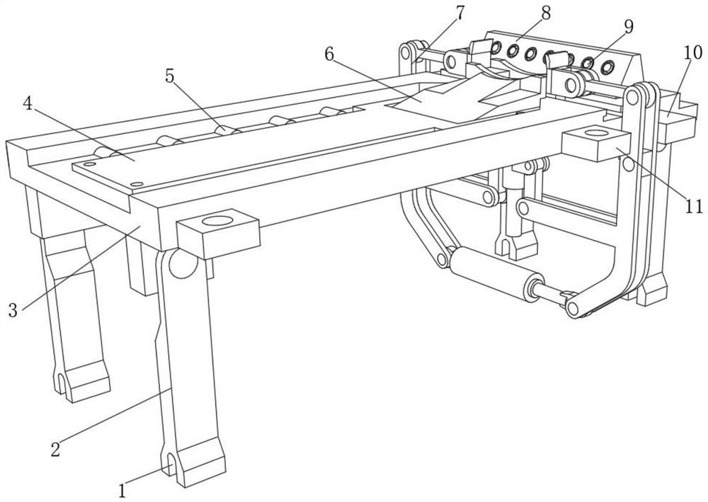
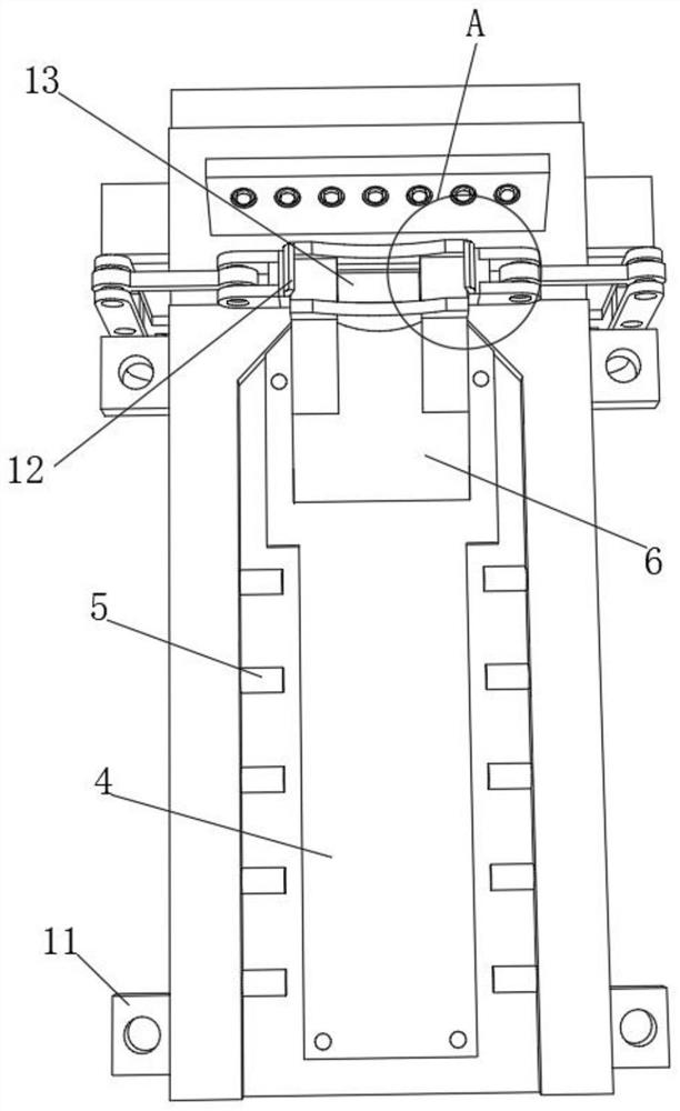
[0035] An auxiliary device for medical examination, such as Figure 1-5 As shown, including the horizontal plate 3, the outer walls of the four corners of the bottom of the horizontal plate 3 are respectively fixed with mounting blocks by bolts, and one side of the outer wall of each mounting block is fixed with a support plate 2 through a rotating shaft, and the bottom outer wall of each support plate 2 is There is a chute 1, and the top outer wall of the horizontal plate 3 is fixed with a sponge pad 4 by bolts, and the top outer walls of the horizontal plate 3 near both sides of the sponge pad 4 are bonded with massage blocks 5;

[0036] The outer walls on both sides of one end of the horizontal plate 3 are fixed with fixed plates 10 by bolts, and the outer wall on one side of the top of the horizontal plate 3 has a guide groove 13, and the outer walls of the two fixed plates 10 near the upper side of the guide groove 13 are provided with automatic clamping. Agency 7;

[00...

Embodiment 2

[0045] A method for using an auxiliary device for medical examination, comprising the following steps:

[0046] S1: Fix the whole device on the CT machine base, and connect the chute 1 at the bottom of each support plate 2 with the conduction rod on the machine base, and install and fix it through four mounting parts 11;

[0047] S2: the patient lies on the sponge pad 4 on the top of the horizontal board 3, and makes the back lean against the inclined backing board 6, and rests the head on the top of the two pillow boards 24;

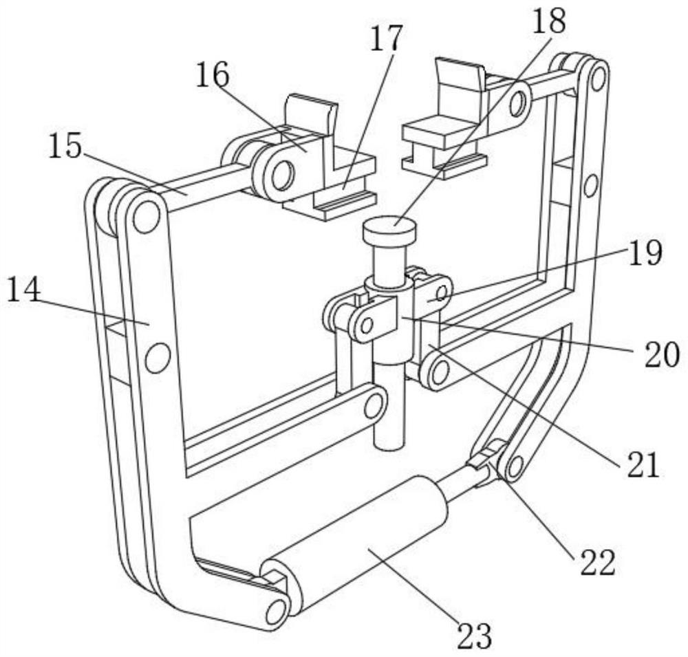
[0048] S3: Start the cylinder 23, the piston rod of the cylinder 23 is extended, which drives the bottom ends of the two sets of L-shaped guide rods 14 to swing to both sides, and the top ends of the two sets of L-shaped guide rods 14 move closer to the inside, and the two L-shaped guide rods 14 The middle end is downward, and through the rotational relationship between the two second connecting rods 21 and the two second fixing pieces 19, the sliding c...


PUM


Abstract

The invention discloses auxiliary equipment for medical examination and a use method of the auxiliary equipment, and relates to the technical field of auxiliary fixing of CT examination. The CT examination efficiency is improved. The device specifically comprises a transverse plate, a mounting block is fixed to the bottom of the transverse plate, a supporting plate is arranged on the outer wall of one side of the mounting block, a sliding groove is formed in the outer wall of the bottom of the supporting plate, a sponge cushion is fixed to the outer wall of the top of the transverse plate, and massage blocks are arranged on the outer walls, close to the two sides of the sponge cushion, of the top of the transverse plate; a guide groove is formed in the outer wall of one side of the top of the transverse plate, an automatic clamping mechanism is arranged on the outer wall of the side, close to the upper portion of the guide groove, of the fixing plate, and limiting cotton pads are arranged at the two ends of the automatic clamping mechanism. According to the CT examination bed, the defects of manual fixation are overcome, the CT examination efficiency is improved, and the patient examination fluency is guaranteed.

Description

technical field [0001] The invention relates to the technical field of medical inspection, in particular to an auxiliary device for medical inspection and a method for using the same. Background technique [0002] At present, when doing CT examination clinically, there is no support and fixation device for the CT machine, and the examinee can only rely on his own body to control it. After a long time, the examinee is very uncomfortable and affects the examination effect. Causing the patient to fall and injure the medical staff greatly increases the difficulty of work. [0003] The Chinese patent application number is CN201920231505.7, which discloses a CT inspection head immobilization device, which is applied to a CT examination bed, including a support body, the support body is U-shaped, and the support body protrudes forward to form a Installation part; two side fixed airbags, symmetrically arranged on both sides of the support body; top fixing assembly, fixedly connecte...

Claims


Application Information

Patent Timeline
Patent Type & Authority Applications(China)
IPC IPC(8): A61B6/04
Inventor 王金秀
Owner 王金秀
Why Eureka
Try Eureka