
Refrigerator and control method thereof

A control method and refrigerator technology, which can be applied to household refrigerators, household refrigeration devices, lighting and heating equipment, etc., can solve the problems of food that cannot be slightly frozen, and reduce nutrient loss, energy consumption, and mechanical damage Effect

Active Publication Date: 2022-04-01
GREE ELECTRIC APPLIANCES INC
View PDF7 Cites 0 Cited by
  • Summary
  • Abstract
  • Description
  • Claims
  • Application Information

AI Technical Summary

Problems solved by technology

[0003] In view of this, the present invention discloses a refrigerator and its control method, which is used to at least solve the problem that the prior art cannot achieve micro-freezing of food

Method used


Image

  • Refrigerator and control method thereof
  • Refrigerator and control method thereof
  • Refrigerator and control method thereof

Examples


Embodiment 1

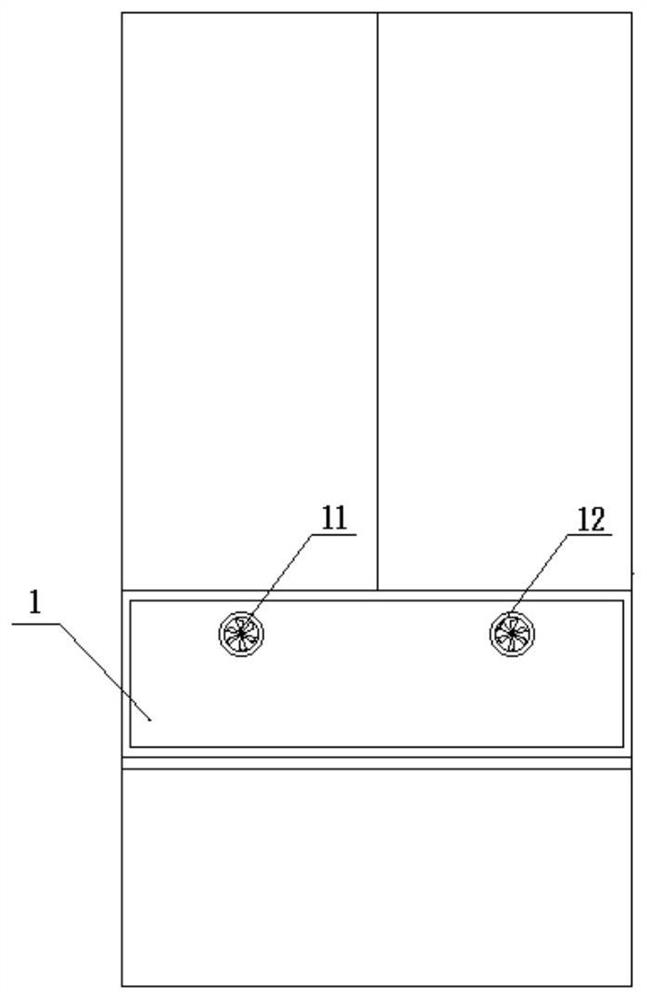
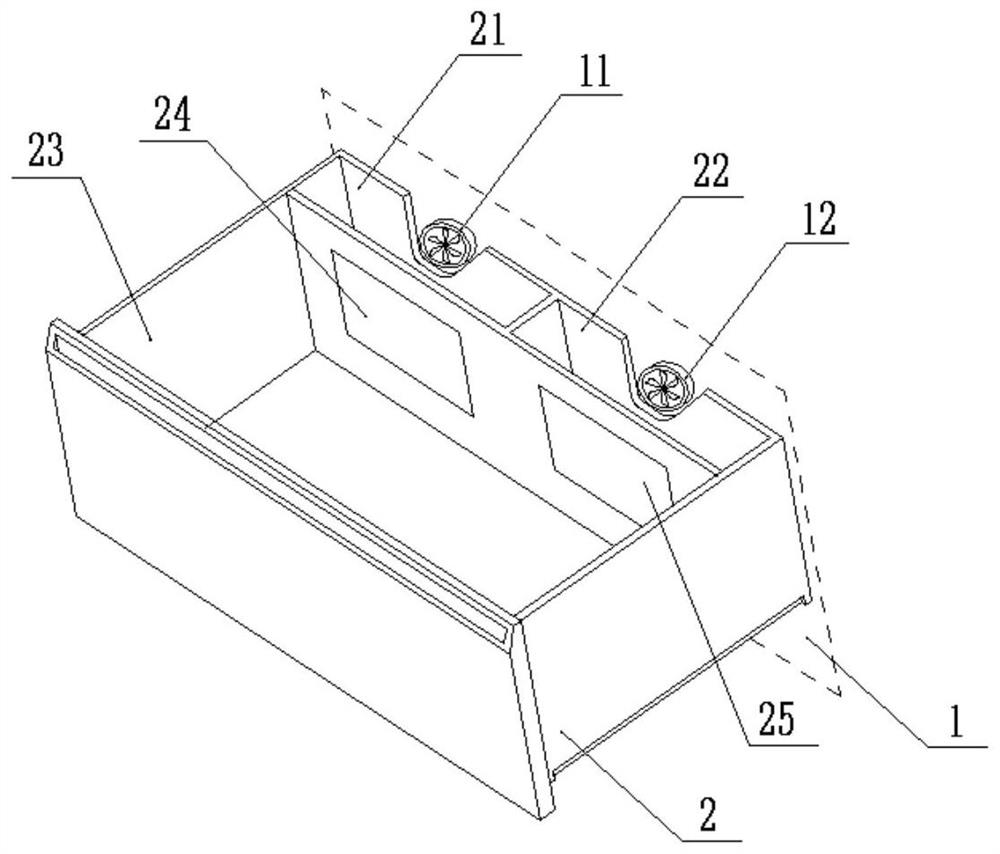
[0064] Such as Figure 1-Figure 2 As shown, a refrigerator is provided in this embodiment, which includes: a refrigerator, a micro-freezing chamber 1 and a freezer, and a refrigerator evaporator corresponding to the refrigerator and a freezer evaporator corresponding to the freezer;

[0065] In the refrigerating room, the air inlet communicates with the room where the evaporator of the refrigerating room is located through the air inlet duct of the refrigerating room, and the air outlet communicates with the room where the evaporator of the refrigerating room is located through the return air duct of the refrigerating room;

[0066] The micro-freezing room 1 includes: a storage room 23 and a first room 21 and a second room 22 communicated with the storage room respectively, wherein the storage room is provided with a first air inlet 24 communicated with the outlet of the first room and connected with the second room. The second air inlet 25 connected to the outlet of the two c...

Embodiment 2

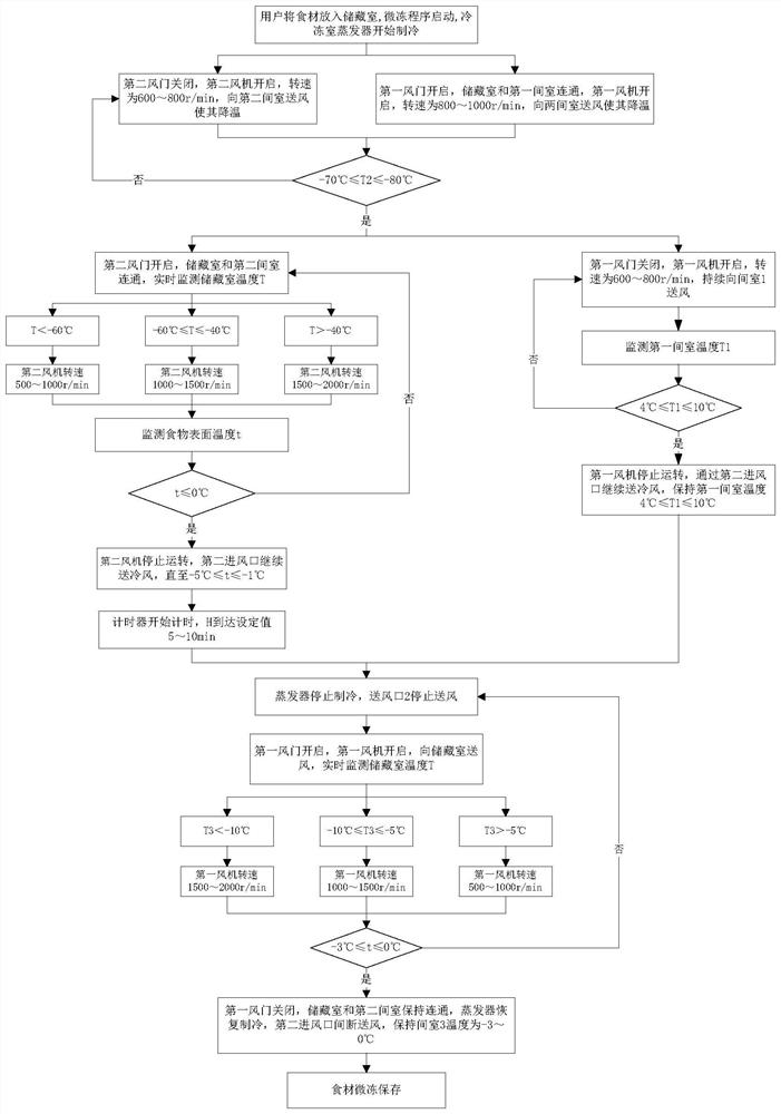
[0076] Such as Figure 1-Figure 4 As shown, in this embodiment, a control method based on the refrigerator in Example 1 is provided. The control method includes: after the refrigerator starts the micro-freezing program, executes the food micro-freezing process, wherein the food micro-freezing process includes:

[0077] Freezing stage: through the first room, refrigerating air is introduced into the micro-freezing room 1 to cool down the food, and the freezing air is stored in the second room. When it is detected that the temperature of the freezing air in the second room reaches the first set temperature , enter the stage of rapid freezing and temperature storage;

[0078] Rapid freezing and temperature storage stage: Stop feeding the refrigeration air into the micro-freezing chamber 1 and store the refrigeration air, pass the freezing air into the micro-freezing chamber 1 and control the cooling rate of the micro-freezing chamber 1 and the food in the micro-freezing chamber 1...


PUM


Abstract

The invention discloses a refrigerator and a control method thereof. The refrigerator comprises a refrigerating chamber, a partial freezing chamber, a freezing chamber, a refrigerating chamber evaporator and a freezing chamber evaporator. An air inlet of the refrigerating chamber is communicated with the refrigerating chamber evaporator through an air inlet duct, and an air outlet of the refrigerating chamber is communicated with the refrigerating chamber evaporator through an air return duct; the partial freezing chamber comprises a storage chamber, a first chamber and a second chamber, the first chamber and the second chamber are communicated with the storage chamber, the storage chamber is provided with a first air inlet communicated with an outlet of the first chamber and a second air inlet communicated with an outlet of the second chamber, an inlet of the first chamber is communicated with the refrigerating chamber air return duct, and an inlet of the second chamber is communicated with the freezing chamber evaporator; an air inlet of the freezing chamber is communicated with the freezing chamber evaporator through an air inlet duct, and an air outlet of the freezing chamber is communicated with the freezing chamber evaporator through an air return duct; the air door assembly comprises a first air door and a second air door; and the fan assembly comprises a first fan arranged at the inlet of the first chamber and a second fan arranged at the inlet of the second chamber.

Description

technical field [0001] The invention relates to the technical field of refrigerators, in particular to a refrigerator and a control method thereof. Background technique [0002] At present, the traditional freezing preservation method is to store meat below the freezing point, so that more than 80% of the water in the meat is frozen to prevent microbial infection and fat oxidation. This method can maximize the storage period of meat, but the food is frozen during the freezing process. In the process, the water will form ice crystals to pierce the cells, resulting in the loss of food nutrients and deterioration of taste. Micro-freeze preservation is a fresh-keeping technology in which the storage temperature is controlled at the freezing point of organisms and at a temperature range of 1-2°C below the freezing point. The basic principle is to use low temperature to inhibit the reproduction of microorganisms and the activity of enzymes, and in a slightly frozen state, part of...

Claims


Application Information

Patent Timeline
Patent Type & Authority Applications(China)
IPC IPC(8): F25D11/02F25D17/06F25D17/08F25D29/00
CPCY02P60/85
Inventor 刘畅赵燕清张茜陈佳弘
Owner GREE ELECTRIC APPLIANCES INC
Learn More