Frame and frame integrated RAT system

An integrated, frame-based technology, applied in the direction of auxiliary power equipment, aircraft parts, transportation and packaging, etc., can solve the problems of large volume, difficult manufacturing, heavy weight, etc., and achieve simple interface, reduce overall weight, and difficult processing low effect

Pending Publication Date: 2022-04-05
JINCHENG NANJING ELECTROMECHANICAL HYDRAULIC PRESSURE ENG RES CENT AVIATION IND OF CHINA
View PDF9 Cites 0 Cited by
  • Summary
  • Abstract
  • Description
  • Claims
  • Application Information

AI Technical Summary

Problems solved by technology

The invention solves the technical problems of heavy weight, large volume, difficult manufacture and difficult assembly brought about by the traditional frame structure

Method used


Image

  • Frame and frame integrated RAT system
  • Frame and frame integrated RAT system
  • Frame and frame integrated RAT system

Examples


Embodiment 1

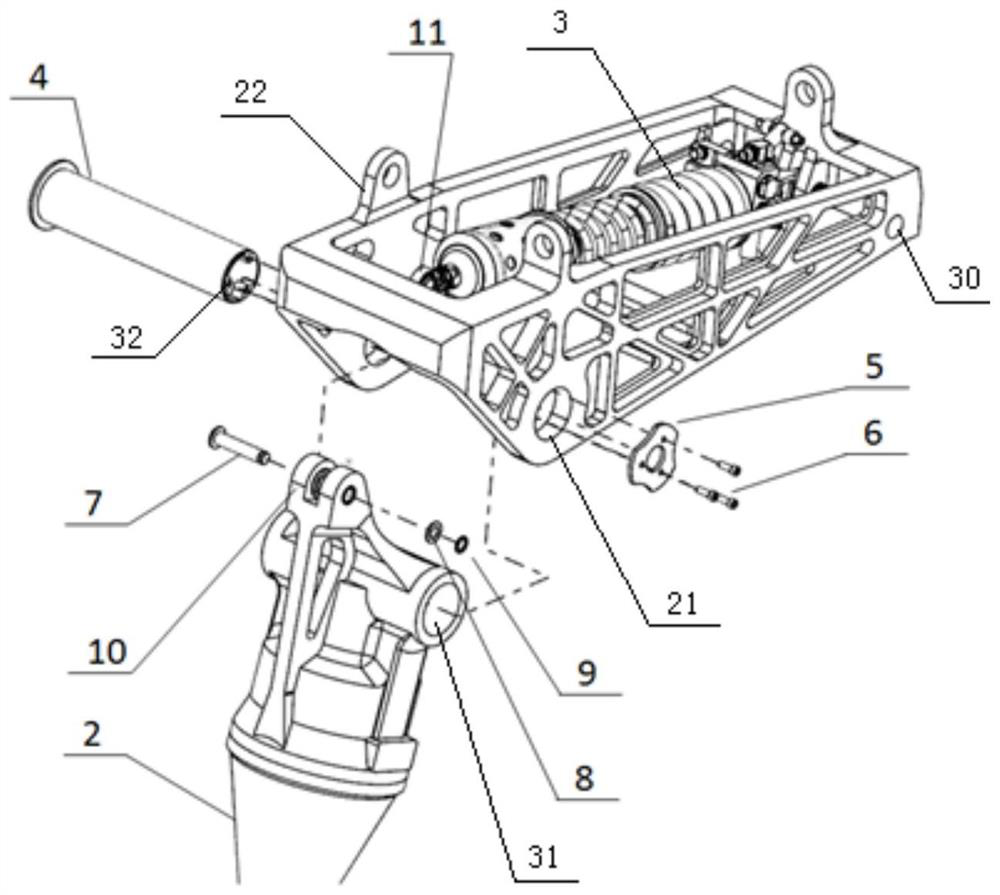
[0029] Example 1. A frame-integrated RAT system, constituted as Figure 1-5 As shown, it includes a pair of frame plates 20 arranged in parallel. The overall shape of the frame plates 20 is an inverted triangle shape. The top corners of the head ends of the two frame plates 20 are connected by the front beam 17. Connected through the lower beam 19, the top corners of the tail ends of the two frame plates 20 are connected through the tail beam 18; the bottom corners of the two frame plates 20 are provided with a coaxial pivot center hole 21; the middle part of the tail beam 18 is provided with Tail beam hanging point interface 15; the frame is integrally formed, and the top of the frame is provided with three aircraft hanging points 22 connected with the aircraft. The one-piece molding is made by 3D printing, which is convenient for the field to replace as a whole, and compared with the one-piece casting, it has higher strength.

[0030] The aforementioned lower beam 19 is pr...

Embodiment 2

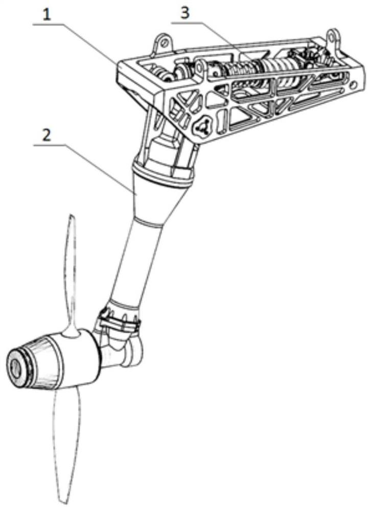
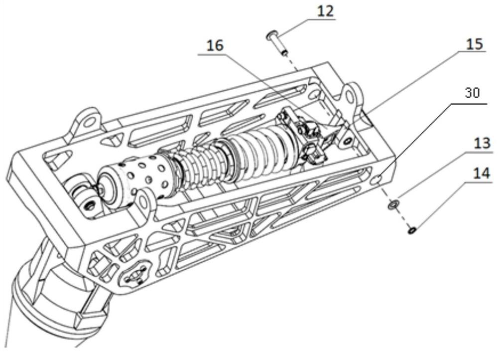
[0040] Example 2. A frame-integrated RAT system, such as figure 1 As shown, it consists of a frame 1, a ram air turbine 2 and a retractable actuator 3, wherein the frame 1 is an integrated structure manufactured by 3D printing. Such as figure 2 As shown, the ram air turbine 2 is mounted on the frame 1 through a pivot 4, a retaining ring I5 and three screws 6. Such as image 3As shown, the tail boom 18 is integrated with the tail boom hanging point interface 15 of the retractable actuator tailstock 16, and the tailstock 16 of the retractable actuator 3 is connected to the tail boom through the pin shaft II12, the washer II13 and the retaining ring III14 On the hanging point interface 15. Such as figure 2 As shown, the ram air turbine 2 is designed with a front seat hanging point interface 10 connected to the front seat of the retractable actuator, and the front seat 11 of the retractable actuator 3 is connected to the front seat hanging point interface through the pin s...


PUM


Abstract

The invention discloses a frame and a frame integrated RAT system. Comprising a pair of frame plates (20) which are arranged in parallel, the whole appearance of each frame plate (20) is in an inverted triangle shape, the top corners of the head ends of the two frame plates (20) are connected through a front beam (17), the positions, close to the bottoms, of the middles of the two frame plates (20) are connected through a lower beam (19), and the top corners of the tail ends of the two frame plates (20) are connected through a tail beam (18). Coaxial pivot center holes (21) are formed in the bottom corners of the two frame plates (20); a tail beam hanging point interface (15) is formed in the middle of the tail beam (18); the frame is of an integrally-formed structure, and three airplane hanging points (22) connected with an airplane are arranged on the top of the frame. The technical problems that a traditional frame structure is heavy in weight, large in size and difficult to manufacture and assemble are solved.

Description

technical field [0001] The invention belongs to the technical field of aviation emergency energy, and in particular relates to a framework and a framework-integrated RAT system. Background technique [0002] The frame structure of a conventional frame-integrated ram air turbine (see Figure 6 ) is composed of two large flat frame plates, a tailstock plate, a front transverse plate, and an upper transverse plate, and other plate structures, and the plates are connected by screws. Because the frame structure bears the impact load of the RAT working process, its strength and rigidity requirements are very high. In order to make up for the lack of strength and rigidity of the plate structure, the size and weight of the traditional frame structure are designed to be large, and it is connected by multiple screws, which has low reliability. In addition, since the frame structure is assembled from multiple parts, there are many cross-linking dimensions between the frame and other c...

Claims


Application Information

Patent Timeline
Patent Type & Authority Applications(China)
IPC IPC(8): B64D41/00
Inventor 周明智杜鑫柯兵谢再茂张敬
Owner JINCHENG NANJING ELECTROMECHANICAL HYDRAULIC PRESSURE ENG RES CENT AVIATION IND OF CHINA
Why Eureka
Try Eureka