Integral spiral non-magnetic drill rod and preparation method thereof

A non-magnetic drill pipe, spiral technology, applied in drill pipe, drilling equipment, drill pipe and other directions, can solve the problems of narrow surface adapting to stratum conditions, weak powder discharge ability, etc., to improve drilling efficiency, low construction noise, The effect of pore wall stabilization

Pending Publication Date: 2022-04-05
XIAN RES INST OF CHINA COAL TECH& ENG GROUP CORP
View PDF0 Cites 0 Cited by
  • Summary
  • Abstract
  • Description
  • Claims
  • Application Information

AI Technical Summary

Problems solved by technology

[0005] In view of the deficiencies in the prior art, the object of the present invention is to provide an integral spiral non-magnetic drill pipe and its preparation method, which solves the problem of weak powder discharge ability and adaptability to formation conditions of the outer flat non-magnetic drill pipe in the prior art narrow problem

Method used


Image

  • Integral spiral non-magnetic drill rod and preparation method thereof
  • Integral spiral non-magnetic drill rod and preparation method thereof
  • Integral spiral non-magnetic drill rod and preparation method thereof

Examples


Embodiment 1

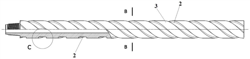
[0050] This embodiment provides a kind of integral helical non-magnetic drill rod, such as Figure 3 to Figure 5 As shown, it includes an outer flat non-magnetic drill rod 1, the outer surface of the outer flat non-magnetic drill rod 1 has a plurality of spiral grooves 2, and spiral fins 3 are formed between the spiral grooves 2;

[0051] The depth H1 of the spiral groove 2 is 5-10mm;

[0052] The width W of the spiral groove 2 is 15-25mm.

[0053] As a preferred solution of this embodiment, there are 1 to 3 spiral grooves 2 .

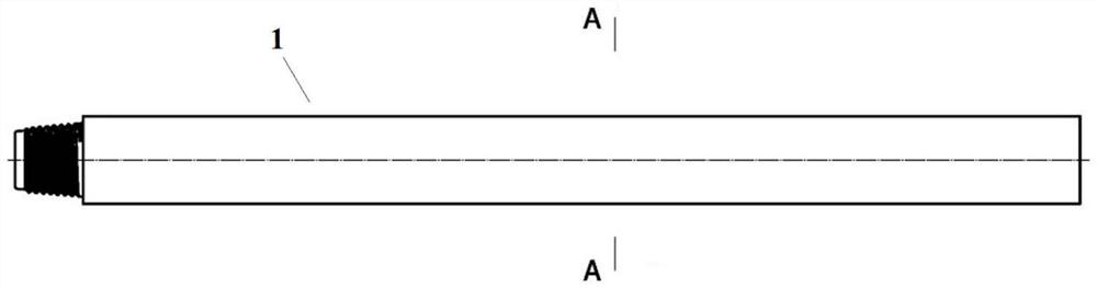
[0054] As a preferred solution of this embodiment, the flattened non-magnetic drill pipe 1 includes a non-magnetic male joint 101 , a non-magnetic drill pipe body 102 and a non-magnetic female joint 103 arranged coaxially in sequence.

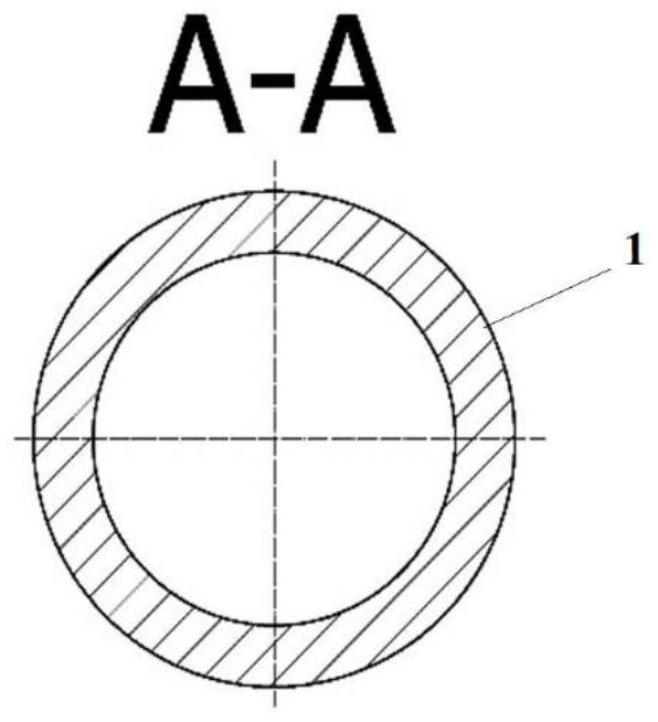
[0055] As a preferred solution of this embodiment, the flat outer non-magnetic drill rod 1 is a hollow structure.

[0056] In this example, if figure 1and figure 2 It can be seen that the surface of the flat non-m...

Embodiment 2

[0060] This embodiment provides a kind of preparation method of integral helical non-magnetic drill rod, and this method comprises the following process:

[0061] Step one, such as Figure 6 As shown, the non-magnetic male joint 101, the non-magnetic drill pipe body 102 and the non-magnetic female joint 103 are welded together by friction welding to form an outer flat non-magnetic drill pipe 1;

[0062] Step two, such as Figure 7 As shown, the spiral groove 2 is milled on the basis of the outer flat non-magnetic drill rod 1, and the milling of the spiral groove 2 is carried out on a CNC milling machine, and the outer flat non-magnetic drill rod 1 is fixed in the Z-axis direction of the milling machine;

[0063] Step three, such as Figure 8 As shown, each helical groove 2 is correspondingly arranged with a milling cutter 4, and the pitch P corresponding to each helical groove 2 is set, and then processed to form, as follows: image 3 The integral helical non-magnetic drill...

Embodiment 3

[0065] This embodiment provides a method for preparing an integral helical non-magnetic drill pipe, which is basically the same as that of Embodiment 2, the only difference being that in step 1, the friction welding in this embodiment adopts the combination of continuous drive friction welding and electric field welding method, such as Figure 11 method shown. And friction welding adopts independent continuous drive friction welding method among the embodiment 2, promptly as Figure 9 method shown.

[0066] Specifically, such as Figure 11 and Figure 12 As shown, the specific process of friction welding using the combined welding method of continuous drive friction welding and electric field is: in this method, the non-magnetic male joint 101, the non-magnetic female joint 103 and the non-magnetic drill pipe body 102 are respectively connected by a friction welding machine tool. 5 Friction welding is completed;

[0067] An annular electrode 6 is set on the nonmagnetic dr...


PUM


Abstract

The invention provides an integral spiral type non-magnetic drill rod and a preparation method thereof, the integral spiral type non-magnetic drill rod comprises an outer flat type non-magnetic drill rod, a plurality of spiral grooves are formed in the outer surface of the outer flat type non-magnetic drill rod, and spiral fins are formed among the spiral grooves; the depth of the spiral groove 2 is 5-10 mm; and the width of the spiral groove 2 is 15-25 mm. A spiral groove is milled on the basis of the outer flat type non-magnetic drill rod, milling of the spiral groove is conducted on a numerical control milling machine, and the outer flat type non-magnetic drill rod is fixed in the Z-axis direction of the milling machine; each spiral groove is correspondingly provided with a milling cutter, the screw pitch corresponding to each spiral groove is set, then machining forming is conducted, and the whole spiral non-magnetic drill rod is obtained. According to the integral spiral non-magnetic drill rod, the continuous spiral fins are formed between the spiral grooves, the powder stirring capacity is high, generated coal powder and chippings can be stirred up through the spiral fins and rapidly discharged into a hole, in-hole accidents such as drill bit locking and drill jamming are not prone to occurring, and the drilling efficiency is greatly improved.

Description

technical field [0001] The invention belongs to the technical field of drilling tools and relates to high-strength stainless steel (non-magnetic steel) materials, in particular to an integral helical non-magnetic drill rod and a preparation method thereof. Background technique [0002] The non-magnetic drill pipe is mainly used to measure the azimuth information of the hole in the directional hole drilling of the coal mine. Its main function is to provide a non-magnetic environment for magnetic measuring instruments to ensure that the magnetic measuring instruments can measure true and accurate geomagnetic field information. Non-magnetic steel drilling tools need to transmit torque to the drill bit. With the development of directional drilling technology, the depth of gas drainage holes in coal mines is getting larger and larger (in 2019, China Coal Science and Technology Group Xi’an Research Institute Co., Ltd. created a 3353m directional drilling hole depth world record),...

Claims


Application Information

Patent Timeline
IPC IPC(8): E21B17/00E21B17/22E21B17/04B23P15/00
Inventor 温国栋鄢忠方路前海马晓琳芦甜朱宁牟培英
Owner XIAN RES INST OF CHINA COAL TECH& ENG GROUP CORP
Why Eureka
Try Eureka