Electrical cabinet automatic inspection system based on infrared temperature measurement imaging

An infrared temperature measurement and automatic inspection technology, applied in electrical components, transmission systems, temperature recording methods, etc., can solve the problems of easy breakage of optical fibers, complicated installation, difficult wiring, etc., to reduce potential safety hazards, improve inspection efficiency, The effect of improving accuracy

Active Publication Date: 2022-04-05
SHANGHAI URBAN CONSTR DESIGN RES INST GRP CO LTD
View PDF0 Cites 0 Cited by
  • Summary
  • Abstract
  • Description
  • Claims
  • Application Information

AI Technical Summary

Problems solved by technology

[0006] In practical applications, the advantage of the luminescent material method is that it is easy to operate and low in price; the disadvantage is that it can only roughly understand the temperature situation, cannot obtain accurate measurement values, and the obtained data is inaccurate
[0007] The advantage of the temperature sensor method is that it can accurately measure the temperature of electrical equipment; the disadvantage is that it needs to be installed in each electrical cabinet, the installation is complicated, and because its information transmission needs to be completed by metal wires, the insulation is poor, and it cannot be applied to high-voltage switch contacts. Point
[0008] The advantage of the optical fiber temperature measurement method is to solve the problem that the temperature sensor cannot be applied to the temperature measurement of the high-voltage switch contact; the disadvantage is that the cost is high, the wiring in the cabinet is difficult, and the optical fiber itself is easy to break, the insulation performance is low, and it is not resistant to high temperature

Method used


Image

  • Electrical cabinet automatic inspection system based on infrared temperature measurement imaging
  • Electrical cabinet automatic inspection system based on infrared temperature measurement imaging

Examples


Embodiment

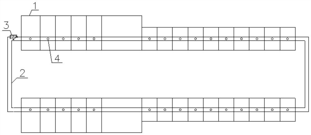
[0035] Such as figure 1 and figure 2 As shown, the automatic inspection system for electrical cabinets based on infrared temperature measurement and imaging includes infrared thermal imaging cameras 3 .

[0036] The infrared thermal imaging camera 3 is arranged on a terminal platform capable of moving along the preset guide rail 2;

[0037] The preset guide rail 2 is set around a plurality of electrical cabinets 1 that need to be inspected, forming a circular track that can circle around a plurality of electrical cabinets 1;

[0038] There is a lifting device on the intelligent platform;

[0039] The lifting device is used to lift the infrared thermal imaging camera 3 to a height corresponding to the infrared transmission window 4 of each electrical cabinet 1;

[0040] Both the terminal platform and the infrared thermal imaging camera 3 are connected to the monitoring cloud platform by wired or wireless means, send the current working status to the monitoring cloud platfor...


PUM


Abstract

The invention discloses an electrical cabinet automatic inspection system based on infrared temperature measurement imaging. The electrical cabinet automatic inspection system comprises an infrared thermal imaging camera; the infrared thermal imaging camera is arranged on a terminal platform capable of moving along a preset guide rail; the preset guide rail is arranged around a plurality of electrical cabinets to be inspected; the intelligent platform is provided with a lifting device used for lifting the infrared thermal imaging camera to the height corresponding to the infrared transmission window of each electrical cabinet. The terminal platform and the infrared thermal imaging camera are connected with the monitoring cloud platform and work according to instructions of the monitoring cloud platform. The method specifically comprises the following steps: 1, setting an inspection path; 2, collecting data; 3, uploading inspection information; 4, data processing; and 5, determining the alarm level and type by using a rule engine, generating alarm information and feeding back the alarm information in real time, and meanwhile, generating a work order to instruct maintenance personnel to process a fault. The application of the invention not only solves the defects of the existing problems, but also improves the accuracy, timeliness, intelligence and feasibility.

Description

technical field [0001] The invention relates to the technical field of electric cabinet detection, in particular to an automatic inspection system for electric cabinets based on infrared temperature measurement and imaging. Background technique [0002] The existing commonly used electrical cabinet temperature measurement methods mainly include luminescent material method, temperature sensor method, and optical fiber temperature measurement method. [0003] The luminescent material method is to select a temperature-sensitive luminescent material and apply it to the electrical equipment that needs to be measured. As the temperature of the electrical equipment changes, the luminescent material can show different colors with the change of temperature. Based on this, the electrical The temperature range of the device. [0004] The temperature sensor method mainly relies on thermal resistors, thermocouples and semiconductor temperature sensors to complete the measurement of the ...

Claims


Application Information

Patent Timeline
Patent Type & Authority Applications(China)
IPC IPC(8): G01J5/48G08B21/18H04L67/06H04Q9/00
CPCY04S10/50
Inventor 罗莹曾冯冯通通谢军黄慰忠
Owner SHANGHAI URBAN CONSTR DESIGN RES INST GRP CO LTD
Why Eureka
Try Eureka