
Molten pool image acquisition method based on spatial filtering technology

A technology of spatial filtering and image acquisition, which is applied in the field of molten pool image acquisition based on spatial filtering technology, can solve the problems of good versatility, low cost, and strong interference of molten pool images, and achieve high reliability, low cost, and clear The effect of the molten pool image

Pending Publication Date: 2022-04-05
SHANGHAI UNIVERSITY OF ELECTRIC POWER
View PDF0 Cites 3 Cited by
  • Summary
  • Abstract
  • Description
  • Claims
  • Application Information

AI Technical Summary

Problems solved by technology

Combining ordinary camera and composite filter technology, this method has the advantages of filtering out a large amount of unnecessary arc light, low cost, and good versatility. The area is dark, and the interference of arc light on the acquisition of molten pool images is strong

Method used


Image

  • Molten pool image acquisition method based on spatial filtering technology
  • Molten pool image acquisition method based on spatial filtering technology
  • Molten pool image acquisition method based on spatial filtering technology

Examples


Embodiment 1

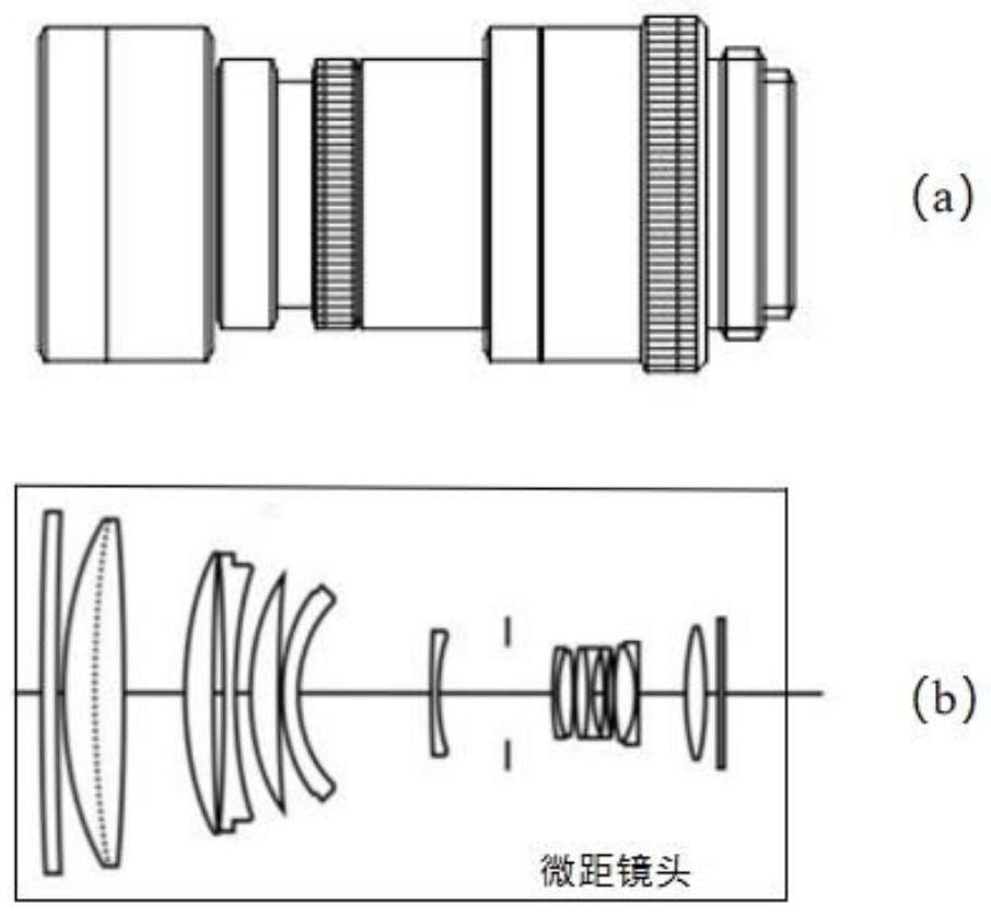
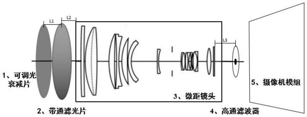
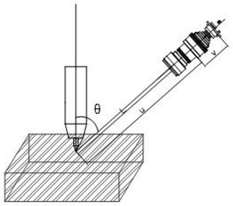
[0048] refer to Figure 1~3 , which is an embodiment of the present invention, provides a method for acquiring images of molten pools based on spatial filtering technology, including:

[0049] S1: Focus the lens, adjust the gear of the neutral density light reduction filter to the initial position, and install the rest of the optical components to the corresponding positions.

[0050] S2: Adjust the shooting angle so that the high-pass spatial filter covers the molten pool, adjust the aperture of the camera lens to change the amount of incoming light, and remove useless background information.

[0051] S3: Adjust the attenuation value of the neutral density light reduction film until the molten pool information is clear.

[0052] S4: The trial welding is finished and welding starts.

[0053] It should be noted that steps S1-S4 specifically include:

[0054] The melting pool feature information acquisition device during the welding process includes a neutral density light re...

Embodiment 2

[0084] refer to Figure 4~5 It is another embodiment of the present invention, which differs from the first embodiment in that it provides a verification test of a melting pool image acquisition method based on spatial filtering technology, in order to verify the technical effect adopted in this method , the present embodiment adopts the method of the present invention to test, and verifies the real effect of the method by means of scientific demonstration.

[0085] A typical melt pool image and its spectrum are shown in Figure 4 As shown, according to the calculation formula of the spectrum component, the width of the low-frequency component is approximately calculated, and the base material size of the high-pass spatial filter is designed according to the camera lens size, and the molten pool spectrum is proportional to the base material, and the metal film of the high-pass filter is designed The size of the layer.

[0086] According to the calculation formula of the rela...


PUM


Abstract

The invention discloses a molten pool image acquisition method based on a spatial filtering technology, and the method comprises the steps: focusing a lens, adjusting the gear of a neutral density dimmer to an initial position, and installing other optical devices at corresponding positions; adjusting a shooting angle to enable the high-pass spatial filter to shield the molten pool, adjusting a self-contained aperture of a camera lens to change the light incoming amount, and removing useless background information; adjusting the attenuation value of the neutral-density dimming sheet until the information of the molten pool is clear; and after test welding is finished, welding is started. The method can effectively remove high-frequency noise and interference in the molten pool image, enhance the edge of the molten pool and remove random noise in the molten pool image, and has the advantages of being high in reliability, low in cost, capable of effectively removing interference noise in the welding process, capable of obtaining a clear molten pool image and the like.

Description

technical field [0001] The invention relates to the technical field of welding automation and intelligence, in particular to a melting pool image acquisition method based on spatial filtering technology. Background technique [0002] With the development of industrialization, the importance of welding technology in aerospace engineering, shipbuilding, vehicle engineering, nuclear industry construction, engineering construction and other fields has become more and more prominent. As a process for permanently joining metal materials, welding is more advantageous when manufacturing large structures or complex machine parts. The molten pool is a pool-shaped liquid metal area formed during the welding process, which contains a large amount of information, which can be used to predict the penetration depth, weld shape, weld defects, etc. Therefore, the use of visual sensing technology to collect images of the molten pool in real time is one of the key technologies to effectively ...

Claims


Application Information

Patent Timeline
Patent Type & Authority Applications(China)
IPC IPC(8): G06V10/147G06V10/30G02B5/28G02B27/00G03B11/00B23K37/00
Inventor 初凤红温豪曾俊冬卞正兰黄琼
Owner SHANGHAI UNIVERSITY OF ELECTRIC POWER
Learn More