
Establishment method of foam system microscopic model

A foam system and microscopic model technology, applied in the fields of instrumentation, computational theoretical chemistry, informatics, etc., can solve problems such as the inability to characterize the evolution process of a circular foam system

Pending Publication Date: 2022-04-05
CHINA UNIV OF PETROLEUM (BEIJING)
View PDF4 Cites 0 Cited by
  • Summary
  • Abstract
  • Description
  • Claims
  • Application Information

AI Technical Summary

Problems solved by technology

[0004] The purpose of the present invention is to provide a method for establishing a microscopic model of the foam system, which can realize the establishment of a complete circular foam system model, and use the circular foam system model established by the technical solution provided by the present invention to carry out molecular simulation research, which can better solve the current problems. There are techniques that cannot characterize the evolution process of an independent and complete circular foam system

Method used


Image

  • Establishment method of foam system microscopic model
  • Establishment method of foam system microscopic model
  • Establishment method of foam system microscopic model

Examples


Embodiment 1

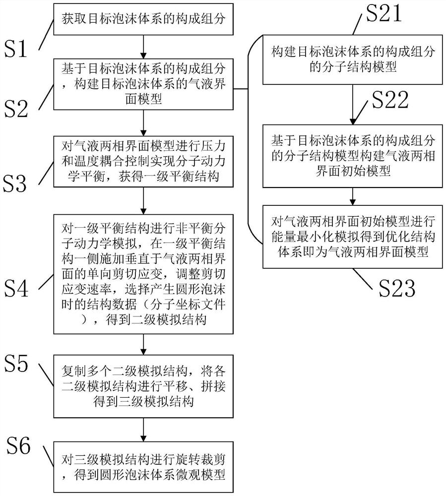
[0084] The present embodiment provides a method for establishing a microscopic model of a foam system, the method comprising:

[0085] 1. Obtain the constituent components of the target foam system; specifically:

[0086] The constituent components of the target foam system include carbon dioxide gas, water, sodium dodecyl sulfate (SDS) foaming agent, and silica nanoparticle foam stabilizer.

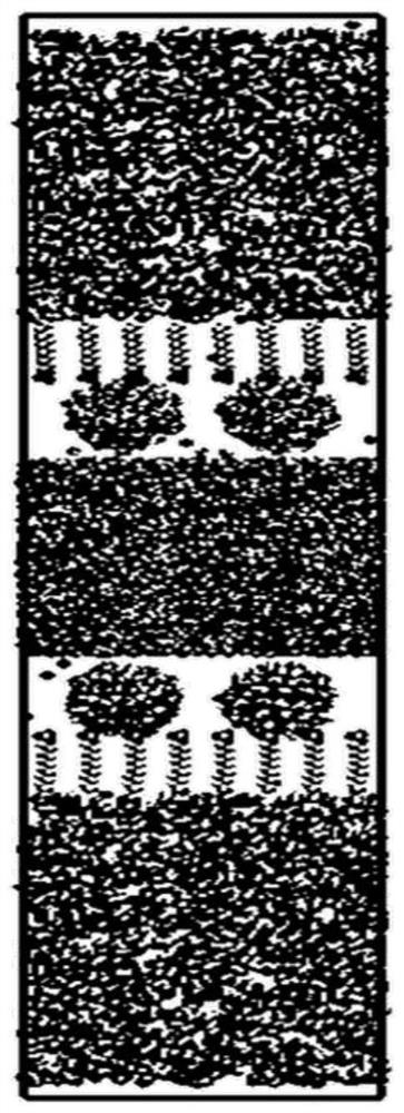
[0087] 2. Use Materials Studio software to build CO 2 Molecular structure model, water molecular structure model, sodium lauryl sulfate molecular structure model, silica nanoparticle molecular structure model; specifically:

[0088] Build CO with Materials Studio software 2 Molecular structure, water molecular structure, sodium lauryl sulfate molecular structure, silica nanoparticle molecular structure, convert the obtained molecular structure coordinates into the input coordinate files required by molecular simulation software, and complete CO 2 Molecular structure model, water molec...


PUM


Abstract

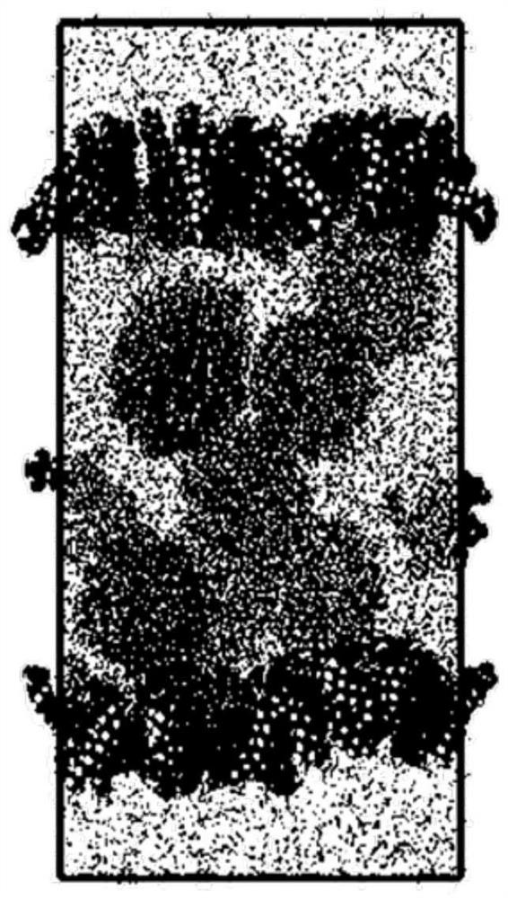
The invention provides a method for establishing a foam system microscopic model. The method comprises the following steps: obtaining components of a target foam system; constructing a gas-liquid two-phase interface model of the target foam system based on the components of the target foam system; performing pressure and temperature coupling control on the gas-liquid two-phase interface model to realize dynamic balance to obtain a first-stage balance structure; performing non-equilibrium molecular dynamics simulation on the first-stage equilibrium structure, applying one-way shear strain perpendicular to a gas-liquid two-phase interface to one side of the first-stage equilibrium structure, adjusting the shear strain rate, and selecting structural data when circular foam is generated to obtain a second-stage simulation structure; copying a plurality of second-level simulation structures, translating the second-level simulation structures, and splicing to obtain a third-level simulation structure; and rotating and cutting the three-stage simulation structure to obtain the micro model of the circular foam system.

Description

technical field [0001] The invention belongs to the technical field of oilfield chemical engineering, and in particular relates to a method for establishing a microscopic model of a foam system. Background technique [0002] During tertiary oil recovery, the use of CO 2 , N 2 The foam system formed by such gases can effectively increase the sweep coefficient during the displacement process and reduce the viscosity of crude oil in the pores, thereby improving the mobility of the remaining oil in the pores of the reservoir and achieving the goal of enhanced oil recovery. [0003] However, the foam system is easy to collapse under high temperature and high pressure reservoir conditions, so improving the stability of foam under reservoir conditions has an extremely important impact on the foam flooding process. In the study of enhancing the stability of foam systems, due to the limitations of space and time scales, traditional experimental methods cannot study the formation-ev...

Claims


Application Information

Patent Timeline
Patent Type & Authority Applications(China)
IPC IPC(8): G16C10/00
Inventor 贾冀辉蔡杭张艳雪朱正杰李经纬彭勃杨磊磊刘琦
Owner CHINA UNIV OF PETROLEUM (BEIJING)
Learn More