Depth-adjustable immersed hydraulic reclamation pipe orifice and hydraulic reclamation method thereof

An adjustable, submerged technology, applied in construction, infrastructure engineering and other directions, can solve the problems of inaccurate sediment accumulation position, easy diffusion of dredged soil, poor ability to resist wind and waves, etc., achieve accurate sediment filling and reduce pollution , the effect of strong environmental adaptability

Pending Publication Date: 2022-04-08
CCCC TIANJIN DREDGING
View PDF0 Cites 0 Cited by
  • Summary
  • Abstract
  • Description
  • Claims
  • Application Information

AI Technical Summary

Problems solved by technology

The invention can solve the problems that the dredged soil is easy to spread in the water body, the pollution range is large, and the sediment accumulation position is not accurate when using the traditional water dredging and filling nozzle, and at the same time, it solves the problem of occupying the barge when using the sand barge to blow and fill the nozzle , Occupying water space, and poor wind and wave resistance, it can improve the efficiency of hydraulic dredgers during filling operations, reduce the spread of dredged soil and pollution to seawater, and improve the accuracy of the accumulation position of dredged soil, which can be widely used in hydraulic power Type dredger water hydraulic conveying throwing and filling project

Method used


Image

  • Depth-adjustable immersed hydraulic reclamation pipe orifice and hydraulic reclamation method thereof
  • Depth-adjustable immersed hydraulic reclamation pipe orifice and hydraulic reclamation method thereof
  • Depth-adjustable immersed hydraulic reclamation pipe orifice and hydraulic reclamation method thereof

Examples


Embodiment

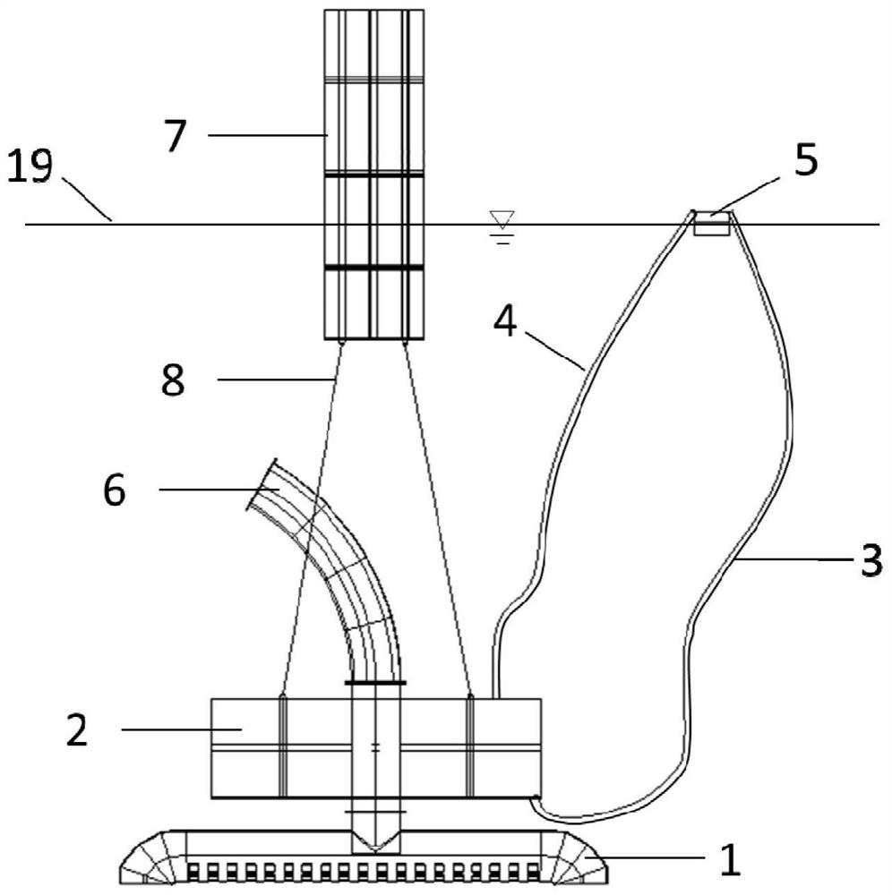
[0034] see Figure 1 to Figure 6 , this embodiment provides a depth-adjustable submerged blow-fill nozzle, including an underwater diffuser 1, an underwater buoy box 2, a long rubber hose 6, a water buoy 7, a water pipe 3, an air pipe 4, and a small buoy 5 and wire rope 8.

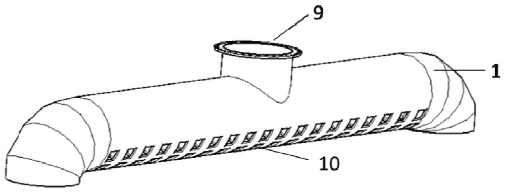
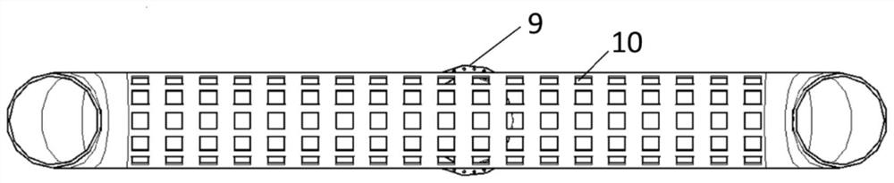
[0035] The underwater diffuser 1 is welded by a horizontal pipe, elbow pipes at both ends of the horizontal pipe and a connecting pipe on the upper part of the horizontal pipe. The bottom of the horizontal pipe is provided with several diffusion holes 10, and the top of the connecting pipe is provided with a flange 9.

[0036] The main surface of the underwater floating tank 2 is welded by steel plates, and the whole is a cubic structure. The middle part of the underwater floating tank 2 has a hole, and a steel pipe is welded at the opening. The upper and lower ends of the steel pipe extend out of the underwater floating tank 2. , the upper and lower ends of the steel pipe are provided with flanges 9; th...


PUM


Abstract

The invention discloses a depth-adjustable immersed hydraulic reclamation pipe orifice and a hydraulic reclamation method thereof. The hydraulic reclamation pipe orifice comprises an underwater diffuser, an underwater buoyancy tank, a long rubber hose, an overwater buoy, a water pipe, a breather pipe, a small buoy and a steel wire rope. A plurality of diffusion holes are formed in the bottom of the underwater diffuser, and an inlet is formed in the upper part of the underwater diffuser; a hole is formed in the middle of the underwater buoyancy tank, a steel pipe is welded to the hole, the upper end and the lower end of the steel pipe extend out of the underwater buoyancy tank respectively, the upper end of the steel pipe is connected with a long rubber hose, and the lower end of the steel pipe is connected with an inlet of the underwater diffuser; the overwater buoy is connected with the underwater buoyancy tank through a steel wire rope; the upper portion and the lower portion of the underwater floating box are respectively provided with a through hole, the upper through hole is connected with a breather pipe, the lower through hole is connected with a water pipe, and the breather pipe and the water pipe are respectively led out of the water surface and then fixed on the small floating cylinder. A certain distance can be kept between the hydraulic reclamation pipe orifice and the water bottom mud surface all the time, silt sprayed out of the pipe orifice can be accumulated at a designated position, and the hydraulic dredger hydraulic reclamation device is widely applied to water hydraulic conveying and dumping projects of hydraulic dredgers.

Description

technical field [0001] The invention belongs to the technical field of dredging engineering, in particular to a depth-adjustable submerged dredging nozzle and a dredging method thereof. Background technique [0002] In some dredging and reclamation projects, it is necessary to throw the dredged soil to the dumping area, which is called underwater dumping. The traditional method is generally to use a ship with a mud tank (such as a mud barge or a suction boat), load the dredged soil into the mud tank and transport it to the designated dumping area, and then open the mud door to dump the dredged soil in the tank to the designated dumping area. Location. However, the disadvantages of this method are as follows: first, the construction operation is discontinuous, and the ship needs a lot of time to go back and forth between the dredging area and the dumping area, and the production efficiency is low; The dredged soil is easy to diffuse and cause large-scale pollution of the wa...

Claims


Application Information

Patent Timeline
IPC IPC(8): E02D15/10
Inventor 李金峰秦亮
Owner CCCC TIANJIN DREDGING
Why Eureka
Try Eureka