Harmonic gear reducer

A gear reducer and harmonic technology, which is applied in the field of harmonic gear reducer, can solve the problems of reduced service life, increased cost, and difficulty in heat dissipation of harmonic gear reducers, so as to reduce frictional resistance, increase service life, and increase sequential effect

Pending Publication Date: 2022-04-08
程林
View PDF0 Cites 2 Cited by
  • Summary
  • Abstract
  • Description
  • Claims
  • Application Information

AI Technical Summary

Problems solved by technology

[0004] However, most of the current harmonic gear reducers have a large transmission ratio, high speed, fast heat generation, and are not easy to dissipate heat. reduce, increase cost

Method used


Image

  • Harmonic gear reducer
  • Harmonic gear reducer
  • Harmonic gear reducer

Examples


Embodiment approach

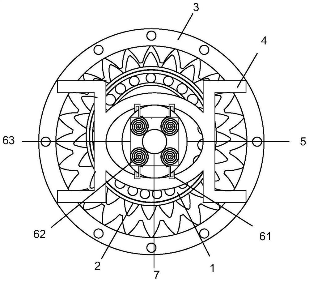
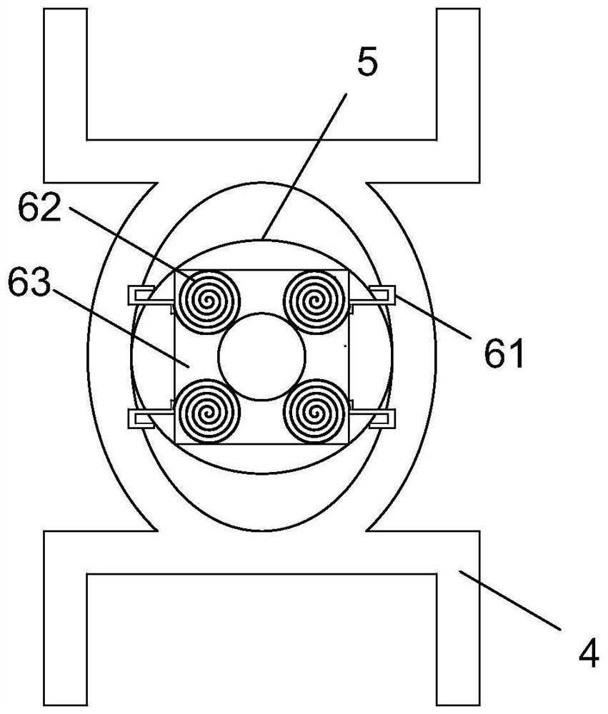
[0026] As an embodiment of the present invention, an air hole 51 is provided at b in the annular air chamber 5, the wall thickness at a in the annular air chamber 5 is set to 10-20 cm, and b in the annular air chamber 5 The wall thickness is set to 3-5cm.

[0027] Because a place in the annular air chamber 5 is the contact part of the fixing mechanism 4 and the annular air chamber 5, so the wall thickness at a in the annular air chamber 5 is set to 10-20cm, which can increase the wear resistance of the annular air chamber 5, thereby increasing the annular air chamber. For the service life of the air chamber 5, the wall thickness at b in the annular air chamber 5 is set to 3-5 cm. When the gas is ejected from the air hole 51 at b, vibration will occur at b in the annular air chamber 5, thereby driving the air hole 51 to vibrate. The movement direction of the ejected gas is disordered, thereby increasing the heat dissipation area, thereby increasing the service life of the harmo...


PUM


Abstract

The invention relates to the field of mechanical transmission, in particular to a harmonic gear reducer which comprises a wave generator, a flexible gear, a steel gear, a fixing mechanism, an annular air bag, a block mechanism and a shaft, the outer wall of the wave generator is connected with the flexible gear in a clamped mode, an outer gear of the flexible gear is meshed with an inner gear of the steel gear, and the steel gear is fixedly connected with the fixing mechanism. A block mechanism is arranged in the fixing mechanism, an annular groove is formed in the outer wall of the block mechanism and matched with an annular air bag, a threaded hole is formed in the middle of the block mechanism, the block mechanism is in threaded connection with a shaft, the shaft is fixedly connected with a wave generator, and the wall thickness of the position a in the annular air bag is larger than that of the position b in the annular air bag. The thickness of the wall at the position a is larger, the abrasion resistance of the annular air bag can be improved, the service life of the annular air bag can be prolonged, the air holes are formed in the position b of the annular air bag, the hole diameters of the air holes are gradually reduced from inside to outside, the air flow speed can be increased in the air spraying process, and therefore heat loss is accelerated, and the dust removal effect is achieved.

Description

technical field [0001] The invention relates to the field of mechanical transmission, in particular to a harmonic gear reducer. Background technique [0002] In the field of mechanical transmission, according to its characteristics, scope of application and use occasions, it can be divided into various reducers. [0003] The harmonic gear reducer is a reducer with simple structure, compact structure, large transmission ratio and high transmission accuracy, so it has been widely used in the field of mechanical engineering. [0004] However, most of the current harmonic gear reducers have a large transmission ratio, high speed, fast heat generation, and are not easy to dissipate heat. Reduce, increase costs. [0005] In view of this, in order to overcome the above problems, the present invention designs a harmonic gear reducer to solve the above problems. Contents of the invention [0006] The technical problem to be solved by the present invention is: the present inventi...

Claims


Application Information

Patent Timeline
Patent Type & Authority Applications(China)
IPC IPC(8): F16H1/32F16H49/00F16H57/04B08B5/02
Inventor 程林王凯旭
Owner 程林
Why Eureka
Try Eureka