
Integrated optical temperature measurement sensing chip, optical temperature measurement sensing equipment and temperature measurement method

A technology integrating optics and sensor chips, applied in the field of precision sensing, can solve the problem of inability to accurately measure the temperature change of integrated optical devices, and achieve the effects of high precision, reduced manufacturing costs, and accurate measurement

Pending Publication Date: 2022-04-08
SOUTH UNIVERSITY OF SCIENCE AND TECHNOLOGY OF CHINA
View PDF0 Cites 0 Cited by
  • Summary
  • Abstract
  • Description
  • Claims
  • Application Information

AI Technical Summary

Problems solved by technology

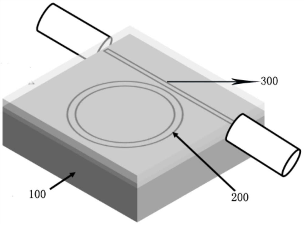
[0005] In view of the above-mentioned deficiencies in the prior art, the object of the present invention is to provide an integrated optical temperature measurement sensor chip, an optical temperature measurement sensor device and a temperature measurement method, aiming at solving the problem that the existing resistance sensor cannot accurately measure the temperature change of the integrated optical device

Method used


Image

  • Integrated optical temperature measurement sensing chip, optical temperature measurement sensing equipment and temperature measurement method
  • Integrated optical temperature measurement sensing chip, optical temperature measurement sensing equipment and temperature measurement method
  • Integrated optical temperature measurement sensing chip, optical temperature measurement sensing equipment and temperature measurement method

Examples


Embodiment Construction

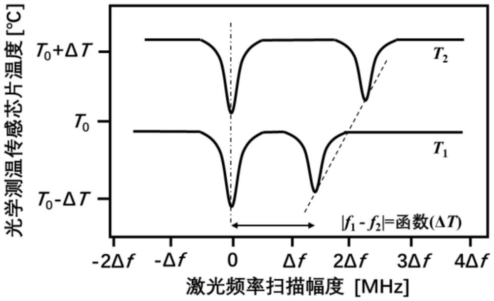
[0026] The optical method is used to measure temperature without introducing additional electronic devices, and will not affect the optical transmission, and its measurement accuracy is also higher than that of thermistor devices. The optical temperature measurement method based on two orthogonal polarization modes uses the difference of the thermo-optic coefficients of the optical mode fields of the two orthogonal polarization directions in the optical device, and reads the optical mode fields of the two orthogonal polarization directions in the optical device. The change of the transmission property in the device can reverse the change of the temperature in the device, so as to realize the accurate measurement of the temperature change. This method has been applied in bench-top Fabry Perot resonators and whispering gallery resonators. However, these optical resonators have large volumes, and the manufacturing process is not compatible with semiconductor processes, so they can...


PUM


Abstract

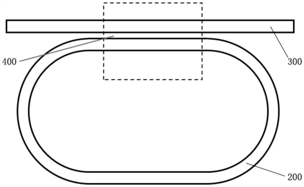
The invention discloses an integrated optical temperature measurement sensing chip, an optical temperature measurement sensing device and a temperature measurement method.The integrated optical temperature measurement sensing chip comprises a wafer substrate and an integrated optical path arranged on the wafer substrate, the integrated optical path comprises a closed-loop integrated optical resonant cavity and an open-loop bus optical waveguide, and the integrated optical resonant cavity is connected with the open-loop bus optical waveguide. A coupling area is formed between the bus optical waveguide and the integrated optical resonant cavity. Based on the principle that the difference between the resonant frequencies of two cross-polarization modes changes along with the change of the temperature of a cavity, the frequency of tunable laser is locked on one polarization resonant frequency of an integrated optical resonant cavity through the PDH (Pound-Drever-Hall) frequency locking technology, the sideband modulation frequency is locked on the difference between the resonant frequencies of the two cross-polarization modes, and the frequency of the tunable laser is locked on the other polarization resonant frequency of the integrated optical resonant cavity through the PDH (Pound-Drever-Hall) frequency locking technology. The real-time tracking of the sideband modulation frequency on the resonant frequency difference of the two cross-polarization modes is realized; by monitoring the change of sideband modulation frequency, the accurate measurement of the temperature change of the integrated optical resonant cavity is realized.

Description

technical field [0001] The invention relates to the technical field of precision sensing, in particular to an integrated optical temperature measurement sensor chip, an optical temperature measurement sensor device and a temperature measurement method. Background technique [0002] Planar integrated optical circuits are widely used in optical communication, quantum optics, nonlinear optics, space-time measurement and other fields. Many sophisticated optoelectronic devices and systems are miniaturized and integrated in the form of integrated optical circuits, so the optical properties of integrated optical devices directly determine the performance of these miniature optoelectronic devices and systems. The thermal stability of integrated optical devices is one of the important factors affecting their optical properties. For example, a change in device temperature will change the refractive index of the material, which in turn affects the propagated optical path and phase dif...

Claims


Application Information

Patent Timeline
IPC IPC(8): G01K11/00H01S5/0239H01S5/0683
Inventor 赵前程
Owner SOUTH UNIVERSITY OF SCIENCE AND TECHNOLOGY OF CHINA
Learn More