Micro-column gel card, sample adding mechanism and method
A micro-column gel card and gel column technology, which is applied in the field of medical devices, can solve problems such as slow detection speed, and achieve the effects of ensuring consistency, increasing the number of columns, and improving detection efficiency
- Summary
- Abstract
- Description
- Claims
- Application Information
AI Technical Summary
Problems solved by technology
Method used
Image
Examples
Embodiment 1
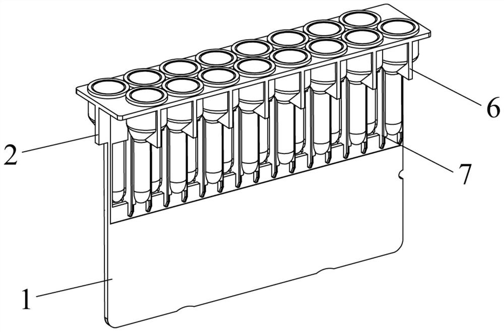
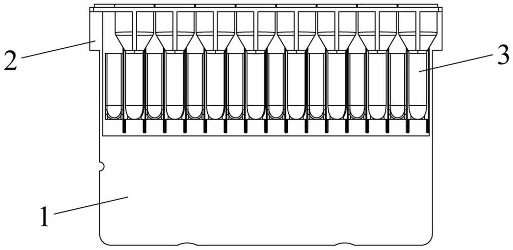
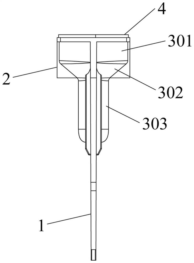
[0046] Such as Figure 1 to Figure 3 As shown, a micro-column gel card includes a fixed plate and some columns 3 arranged and fixed by the fixed plate, the plurality of columns are respectively fixed on both sides of the fixed plate, and the tubes on both sides of the fixed plate The columns are arranged in a dislocation manner, and any one of the tube columns 3 includes a sample loading chamber 301, a reaction chamber 302 and a gel column 303, the gel column 303 is used to load gel reagents, and the sample loading chamber 301 is arranged in the Above the gel column 303, the reaction chamber 302 is connected between the sample loading chamber 301 and the gel column 303, and the central axes of the sample loading chamber 301 and the gel column 303 do not coincide.
[0047] There is a certain dislocation relationship between the columns distributed on both sides of the fixed plate, and any two adjacent columns do not overlap, so as to ensure that the microcolumn gel card is used...
Embodiment 2
[0049] Such as figure 2 and Figure 4 As shown, in one embodiment, the number of columns on both sides of the fixed plate is equal and eight, forming a double-row sixteen-hole micro-column gel card. The columns on both sides of the fixed plate present a centrally symmetrical form, and the gel column The vertical projection of the sample chamber is internally tangent, and any two gel columns are parallel to each other and the front projections do not overlap. The column on the side of the fixed plate is set as the first column group ( Figure 4 The one in the upper row is the first pipe string group), and the pipe string on the other side is the second pipe string group ( Figure 4 Shown in the lower row is the first string group), such as Figure 4 As shown, the eight strings of the first string group are set to be H1~H8 respectively, and the eight strings of the second string group are set to be M1~M8 respectively, and the centers of any two adjacent strings distances are...
Embodiment 3
[0068] In this embodiment, the sample loading mechanism 5 has degrees of freedom of movement in X, Y, and Z directions, and the sample loading mechanism 5 includes four sample loading devices (such as Figure 6 The corresponding schematic diagram is shown, it should be noted that, Figure 6 It is a schematic diagram of the principle drawn to illustrate the technical effect of this embodiment, and does not represent the actual structural relationship), which are respectively the first sampling device 501, the second sampling device 502, the third sampling device 503 and the fourth sampling device 504, the distance between any two adjacent sampling devices is twice the center-to-center distance of adjacent columns, which is 2d, and the sampling mechanism should condense the double-row sixteen-hole microcolumn The method of adding samples to the plastic card is as follows: Figure 8 Shown:
[0069] S8: the sample loading mechanism moves to the top of the microcolumn gel card; ...
PUM
| Property | Measurement | Unit |
|---|---|---|
| depth | aaaaa | aaaaa |
| depth | aaaaa | aaaaa |
Abstract
Description
Claims
Application Information
 - R&D
- Intellectual Property
- Life Sciences
- Materials
- Tech Scout
- Unparalleled Data Quality
- Higher Quality Content
- 60% Fewer Hallucinations
Browse by: Latest US Patents, China's latest patents, Technical Efficacy Thesaurus, Application Domain, Technology Topic, Popular Technical Reports.
© 2025 PatSnap. All rights reserved.Legal|Privacy policy|Modern Slavery Act Transparency Statement|Sitemap|About US| Contact US: help@patsnap.com


