Photoelectric detector device, design method and wireless optical communication system

A technology of photodetector and design method, which is applied in the field of optical communication, can solve the problems of increasing system noise, increasing system complexity and cost, reducing joint bandwidth, etc., to improve receiving performance, increase effective light-receiving area, increase The effect of the receiving aperture

Pending Publication Date: 2022-04-08
PURPLE MOUNTAIN LAB
View PDF0 Cites 0 Cited by
  • Summary
  • Abstract
  • Description
  • Claims
  • Application Information

AI Technical Summary

Problems solved by technology

[0006] There are other ways to improve the performance of the receiving end: 1. Connecting multiple photodiodes in parallel can increase the photocurrent generated jointly, but it will inevitably increase their capacitance. Although it is equivalent to increasing the active receiving area, the joint bandwidth is reduced.
2. An angle diversity receiver (ADR, Angle diversity receiver) deploying multiple photodiodes can produce a larger aperture and a wider field of view, but each photodiode requires a separate preamplifier, which not only increases the system complexity and cost, also increases system noise

Method used


Image

  • Photoelectric detector device, design method and wireless optical communication system
  • Photoelectric detector device, design method and wireless optical communication system
  • Photoelectric detector device, design method and wireless optical communication system

Examples


Embodiment 1

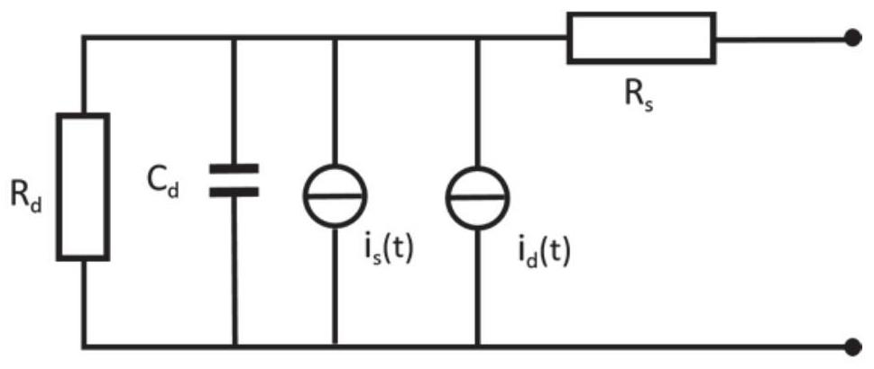
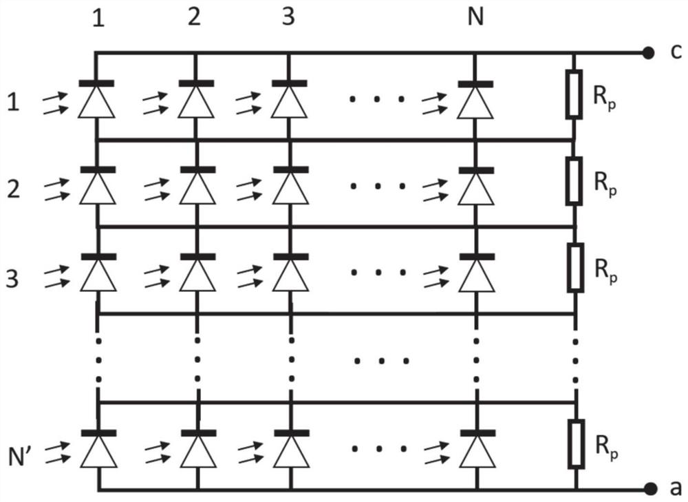
[0035] A design method of a photodetector device. The photodetector device includes a photodiode matrix and several cascaded resistors. N photodiodes are connected in parallel to form a 1×N parallel PD (photodiode) matrix, and then a cascaded resistor is connected in parallel. resistance;

[0036] The parallel PD matrix after N' parallel cascaded resistors is connected in series;

[0037] Both ends of the cascaded resistors connected in series are output terminals for outputting one electrical signal.

[0038] Through the above design, the light-receiving area can be effectively increased, and the light-receiving performance can be improved.

[0039] The output of the photodiode matrix is ​​used to interface with the amplification circuit.

[0040] The number N' of the cascaded resistors is not less than the total column number N of the parallel PD matrix, and the resistance value of the cascaded resistors satisfies the bandwidth compensation condition, and the bandwidth com...

Embodiment 2

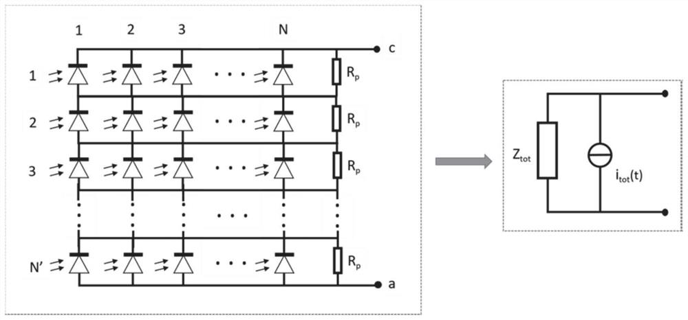
[0050] A photodetector device, including a photodiode matrix and several cascaded resistors, the photodiode matrix includes N×N′ photodiodes, N photodiodes are connected in parallel to form a 1×N parallel PD matrix, and then a parallel connection The cascaded resistors are connected in series with the parallel PD matrices after N′ parallel cascaded resistors, and the two ends of the series connected cascaded resistors are output terminals for outputting one electrical signal.

[0051] The device can effectively increase the light-receiving area and improve the light-receiving performance.

[0052] Further, the number N' of the cascaded resistors is not less than the total number N of columns of the parallel PD matrix, and the resistance value of the cascaded resistors meets the bandwidth compensation condition.

[0053] When the device satisfies the above conditions, the effective light-receiving area is increased without reducing the bandwidth, and the light-receiving performan...

Embodiment 3

[0087] In this embodiment, a 2×2 photodiode matrix is ​​designed, which is composed of two 1×2 photodiode matrices, as shown in the attached Figure 5 shown. Each photodiode has an effective area diameter of 100um and supports 2.5Gbit / s. It can be interconnected by wire bonding and packaged in a thin TO-46 can, which can be flexibly used at the receiving end of the wireless optical system, increasing the effective receiving area without changing the bandwidth, and enhancing the performance of the receiving end of the system. At this time, compared with a single receiving PD, the effective light-receiving area increases by 4 times, the output current increases by 2 times, and the bandwidth remains basically unchanged. In addition, the entire matrix still maintains one signal output in the end. The PD matrix generally used in laser communication in the prior art finally outputs multiple signals. For example, if the matrix includes 8 PDs, 8 signals are transmitted respectively. ...


PUM


Abstract

The invention discloses a photoelectric detector device, a design method and a wireless optical communication system, the photoelectric detector device comprises a photodiode matrix and a plurality of cascade resistors, the photodiode matrix comprises N * N'photodiodes, the N photodiodes are connected in parallel to form a 1 * N parallel PD matrix, then the 1 * N parallel PD matrix is connected in parallel with a cascade resistor, and the 1 * N parallel PD matrix is connected in parallel with the cascade resistor. The N'parallel PD matrixes connected in parallel with the cascade resistors are connected in series, and the two ends of the cascade resistors connected in series are output ends used for outputting one path of electric signals. The light receiving aperture of the photoelectric detector device can be increased, the effective light receiving area is increased, the light receiving performance is improved, and the bandwidth is not reduced.

Description

technical field [0001] The invention relates to the technical field of optical communication, in particular to a photodetector device, a design method and a wireless optical communication system. Background technique [0002] At present, in the existing wireless communication system, the wireless spectrum has been saturated and has become an extremely precious resource. Therefore, the development and utilization of new spectrum resources is an inevitable trend in the future development of wireless communications. [0003] Free Space Optical Communications (FSO) is an important part of Optical Wireless Communication (OWC). The wireless laser communication system uses light waves as the carrier of signal transmission to achieve high-speed and reliable transmission of information in space. . Wireless optical communication technology overcomes the shortcomings of the lack of spectrum resources in traditional radio frequency communications. Relying on its own rich spectrum reso...

Claims


Application Information

Patent Timeline
Patent Type & Authority Applications(China)
IPC IPC(8): H01L27/144H04B10/11H04B10/60
Inventor 曹珂朱世程张启王家恒高西奇孙晨
Owner PURPLE MOUNTAIN LAB
Why Eureka
Try Eureka