
A kind of super linear loudspeaker and its test equipment

A technology for testing equipment and speakers, applied in the direction of sensors, electrical components, etc., can solve the problems of worse acoustic performance of the whole machine, shaking of speaker modules, and increased vibration, etc., to increase precision performance, reduce flow noise, and increase locking. effect of time

Active Publication Date: 2022-08-05
浙江豪声电子科技股份有限公司
View PDF8 Cites 0 Cited by
  • Summary
  • Abstract
  • Description
  • Claims
  • Application Information

AI Technical Summary

Problems solved by technology

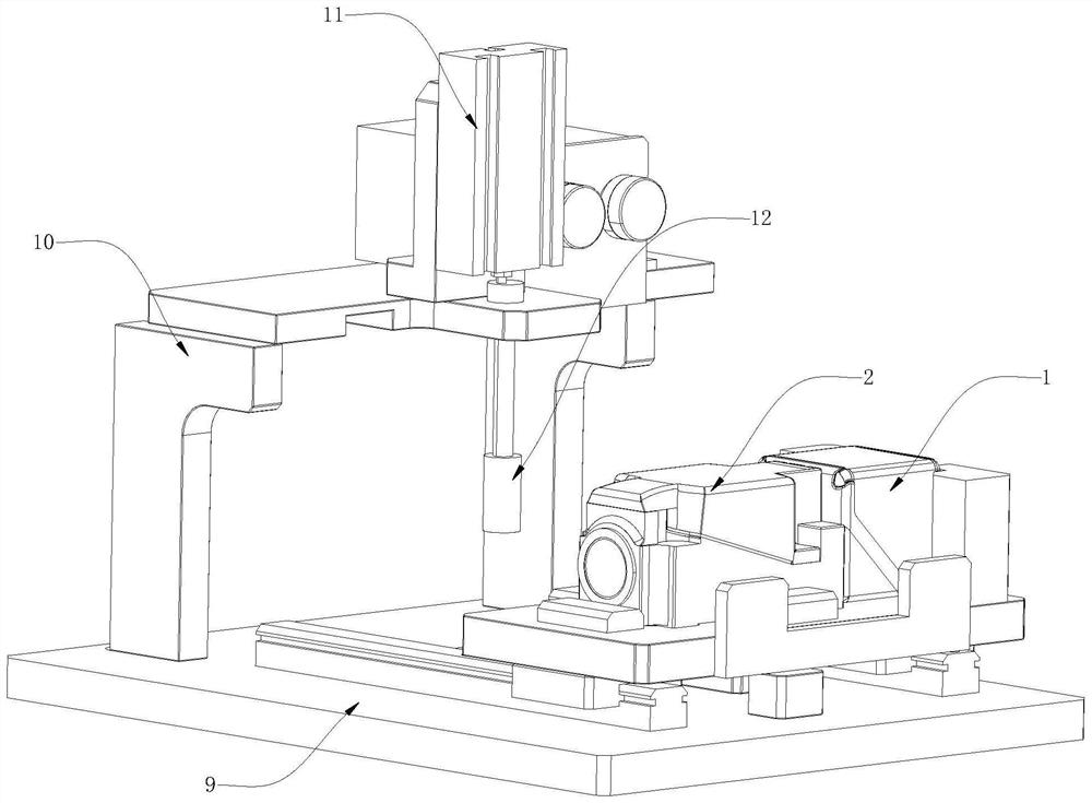
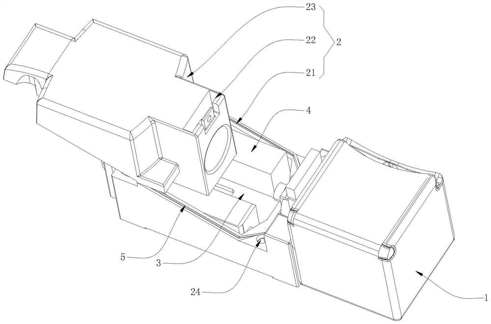
[0005] However, there are the following problems in the process of use: the sound outlet and leakage port of the speaker module are blocked by the spacer, the cover plate is placed on the base, and the cover plate and the base are enclosed to form a closed detection space. Under the force of loud vibration, the above-mentioned blocking and connecting points are subject to the resonance effect from the frequency response of the speaker module, which will intensify the vibration around the connecting points and the upper and lower shells and collide with each other to generate noise, and when the airflow passes through the gap Noises such as airflow sound are generated, which affect the listening of the module. Due to the mutual support of airflow and vibration, the speaker module placed on the tooling body will vibrate, causing the speaker module in the storage tank to shake, causing the speaker module to vibrate. When the group produces tiny gaps during the welding or bonding process and has not been detected, after assembly in the above-mentioned detection space, it is continuously driven by the force generated by the module when it is working, and the original seal is not tight. The gap will continue to grow, making the acoustic performance of the whole machine gradually worse

Method used


Image

  • A kind of super linear loudspeaker and its test equipment
  • A kind of super linear loudspeaker and its test equipment
  • A kind of super linear loudspeaker and its test equipment

Examples


Embodiment Construction

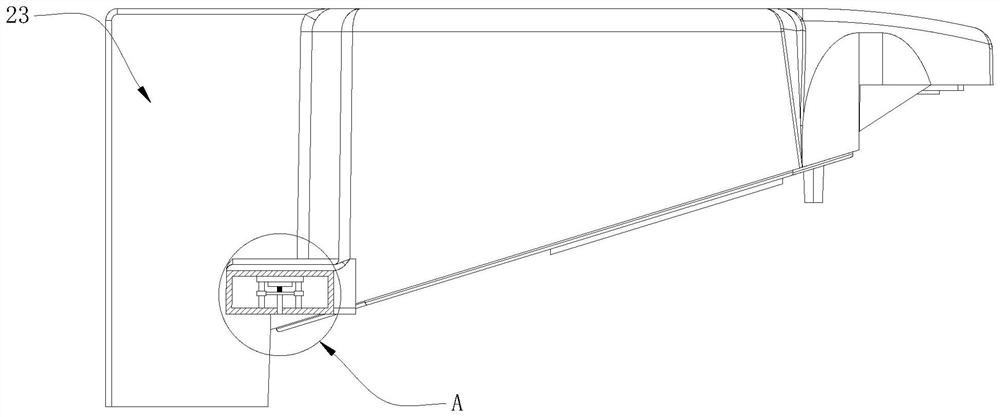
[0040] The technical solutions in the embodiments of the present invention will be clearly and completely described below with reference to the accompanying drawings in the embodiments of the present invention. Obviously, the described embodiments are only a part of the embodiments of the present invention, but not all of the embodiments. Based on the embodiments of the present invention, all other embodiments obtained by those of ordinary skill in the art without creative efforts shall fall within the protection scope of the present invention.

[0041] In this example, refer to Figure 11 As shown, it includes a speaker module 13. The speaker module 13 consists of a protective cover 131, a connecting portion 132, a diaphragm 133, a conversion system 134 and a magnetic member 135. The protective cover 131 is a cavity-like structure, and the following structures are installed: The connecting part 132 is connected to one side inside the protective sleeve 131 , one side of the co...


PUM


Abstract

The invention discloses a super-linear loudspeaker and testing equipment thereof, and relates to the technical field of super-linear loudspeaker testing equipment. The fixed cavity, the through piece and the sliding portion are in a sliding shape relative to the fixed cavity, and one side of the through piece and the sliding portion is integrally formed. In the above scheme, the magnetic parts located on both sides of the sliding part are powered off, and the compression spring located on one side of the magnetic part is in a compressed state when the magnetic part is energized, which effectively prevents vibration effects during the test process. The upper and lower shells will vibrate and collide with each other and dislocate, thus affecting the detection effect of the test object, effectively increasing the locking time of the upper and lower shells, and improving the tightness between the fixed cavity and the sliding part, reducing It eliminates the flow noise when the airflow collides through the gap between the shells, and increases the accuracy of the test object.

Description

technical field [0001] The invention relates to the technical field of super-linear loudspeaker testing equipment, in particular to a super-linear loudspeaker and its testing equipment. Background technique [0002] With the rapid development of mobile phone technology, the traditional speakers built in mobile phones are gradually replaced by super-linear speakers. Compared with traditional speakers for mobile phones, super-linear speakers have lower total harmonic distortion, can withstand relatively higher power, The conversion of electromagnetic energy into sound energy has many advantages, and it is increasingly favored in the field of mobile phone applications. [0003] In order to ensure the reliability of the product, the product needs to be sealed without leakage in the design of the glue coating position, ultrasonic welding line, in-mold injection steel sheet, etc. except for the sound outlet and leakage port. The manufacturer needs to test the air tightness of the...

Claims


Application Information

Patent Timeline
Patent Type & Authority Patents(China)
IPC IPC(8): H04R29/00H04R9/04H04R9/06
Inventor 虎浩月李中进王震杰罗瑞
Owner 浙江豪声电子科技股份有限公司
Learn More