Drivable spiral progressive low-injury integrated bone puncture needle

A low-injury, one-piece technology, used in puncture needles, trocars, internal bone synthesis, etc., can solve the problems of pedicle and vertebral body injury, reduced puncture success rate, increased surgical risk, etc. The effect of destroying, reducing surgical complications, and simplifying surgical procedures

Inactive Publication Date: 2022-04-12
张峻玮
View PDF0 Cites 0 Cited by
  • Summary
  • Abstract
  • Description
  • Claims
  • Application Information

AI Technical Summary

Problems solved by technology

[0002] Percutaneous puncture vertebroplasty is currently a common surgical method for the treatment of senile osteoporotic compression fractures. It has the characteristics of small trauma, quick recovery, and remarkable effect. However, the puncture system used in clinical surgery usually requires a fine puncture Needle puncture for positioning, then insert the secondary sleeve on the positioning needle, smash it into the bone with a bone hammer, then insert the third-level sleeve on the second-level sleeve, and use the bone hammer again to smash the third-level sleeve. The tube is smashed into the bone to establish a working channel for bone cement delivery. Multiple punctures may easily cause bone damage on the surface of the puncture point. If a thick puncture needle is directly used for positioning, because the needle shaft is relatively thick, direct knocking into the bone may cause secondary fractures. Once the puncture is in, the direction is difficult to change, the success rate of puncture is reduced, and the risk of surgery is increased. At the same time, most of the puncture needles are violently smashed into the vertebral body by a bone hammer. Due to old age osteoporosis, it is easy to cause pedicle and vertebra damage to the body, thereby causing risks such as bone cement leakage and spontaneous bleeding

Method used


Image

  • Drivable spiral progressive low-injury integrated bone puncture needle
  • Drivable spiral progressive low-injury integrated bone puncture needle
  • Drivable spiral progressive low-injury integrated bone puncture needle

Examples


Embodiment Construction

[0029] Attached below Figure 1-8 The present invention is described in further detail.

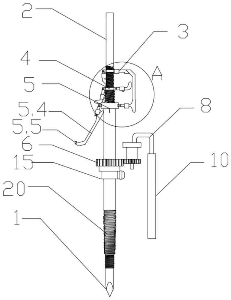
[0030] A drivable spiral progressive low-injury integrated bone puncture needle, comprising:

[0031] A bone spur needle body, one end of the body is provided with a tapered tip 1, and the other end of the body is provided with a threaded assembly section 2;

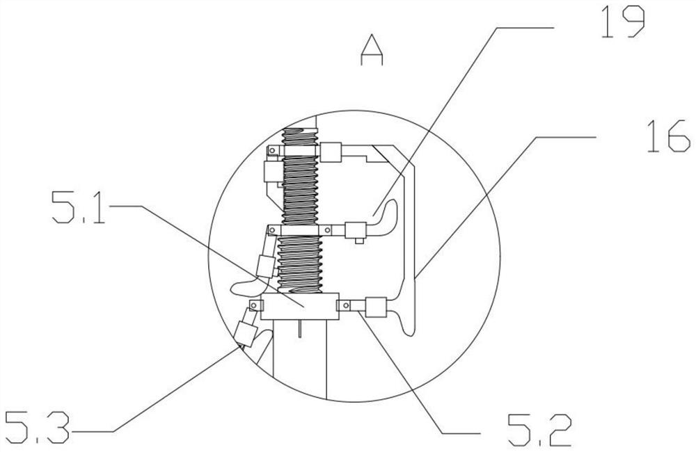
[0032] The assembly section 2 is sequentially screwed with an outer rod handle 3, a middle rod handle 4 and an inner rod handle 5, and the inner rod handle 5 is set to be openable;

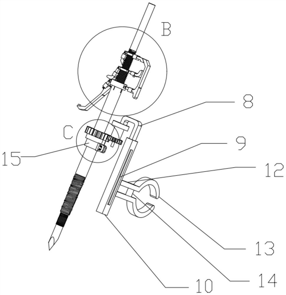
[0033] A connection mechanism is provided on the main body and between the tip part 1 and the inner rod handle 5. The connection mechanism includes a detachable gear 6, a fixed locking part for limiting the gear 6 and an adjustable clip connected to the gear 6. Connecting part, the clamping part is used for clamping the hospital bed.

[0034] In the process of specific implementation, open the outer rod handle 3, and the fully opened state can be use...


PUM


Abstract

The invention discloses a drivable spiral progressive low-injury integrated bone puncture needle which comprises a bone puncture needle main body, one end of the main body is provided with a conical tip part, and the other end of the main body is provided with an assembly section with threads; an outer rod handle, a middle rod handle and an inner rod handle are sequentially connected to the assembling section in a screwed mode, and the inner rod handle is arranged to be in an opening type. A connecting mechanism is arranged on the main body and located between the tip part and the inner rod handle, the connecting mechanism comprises a detachable gear, a fixed locking part for limiting the gear and an adjustable clamping part connected to the gear, and the clamping part is used for clamping a sickbed. The percutaneous puncture needle is high in practicability and functionality and can be widely applied to the technical field of percutaneous puncture.

Description

technical field [0001] The invention relates to the field of percutaneous puncture, in particular to a drivable spiral progressive low-damage integrated bone puncture needle. Background technique [0002] Percutaneous puncture vertebroplasty is currently a common surgical method for the treatment of senile osteoporotic compression fractures. It has the characteristics of small trauma, fast recovery, and remarkable effect. However, the puncture system used in clinical surgery usually requires a fine puncture Needle puncture for positioning, then insert the secondary sleeve on the positioning needle, smash it into the bone with a bone hammer, then insert the third-level sleeve on the second-level sleeve, and use the bone hammer to smash again, and put the third-level sleeve into the bone. The tube is smashed into the bone to establish a working channel for bone cement delivery. Multiple punctures may easily cause bone damage on the surface of the puncture point. If a thick pun...

Claims


Application Information

Patent Timeline
IPC IPC(8): A61B17/34A61B17/70A61B90/00
Inventor 张峻玮李华曹贞国魏东王云清
Owner 张峻玮
Why Eureka
Try Eureka