Steam condensation method

A technology of steam condensation and steam, which is applied in the direction of steam condensation, separation methods, chemical instruments and methods, etc. It can solve the problems of large water discharge of cooling towers, idling of water pumps, and affecting heat exchange efficiency, etc., to achieve fast heat exchange efficiency, Effect of reducing intermediate conversion loss

Pending Publication Date: 2022-04-12
苏州赢众环保有限公司
View PDF12 Cites 1 Cited by
  • Summary
  • Abstract
  • Description
  • Claims
  • Application Information

AI Technical Summary

Problems solved by technology

[0003] Problems in the existing technology: 1. Below zero temperature in winter, the water freezes and cannot be used; 2. The cooling circulation water pipe freezes and cracks often occurs below zero temperature in winter; 3. The filling of the cooling tower is not resistant to high temperature and will melt Phenomenon; 4. Sludge fouling will occur in the cooling water pipe when it is used for a long time; 5. Calcium carbonate scaling will occur in the condenser after using it for a long time, which will seriously affect the heat exchange efficiency; 6. The cooling tower will discharge hot water and affect the Environmental perception; 7. The cooling tower is prone to lack of water, which will cause the water pump to run idly, etc.

Method used


Image

  • Steam condensation method
  • Steam condensation method

Examples


Embodiment 1

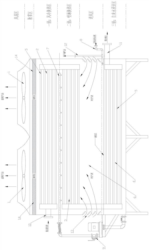
[0027] refer to Figure 1-2 , the steam condensation and heat dissipation integrated equipment in this embodiment includes a fan 1, a primary heat exchange area (device) 2, a secondary heat exchange area (device) 3, an air inlet area 6, and a third stage heat exchange area (device) ) 4. The defogging layer 14 arranged between the fan 1 and the first-stage heat exchange area 2, the water inlet pipe 8 set corresponding to the third-stage heat exchange area 4, and the air inlet 13 arranged corresponding to the air inlet area 6 are used for the second The spray pipeline 7 for spraying and cooling in the first-stage heat exchange area 3, the water pump 9 connecting the third-stage heat exchange area 4 and the spray pipe 7, and the air intake pipe 10 arranged at one end of the heat exchange pipe 5 in the first-stage heat exchange area 2 , a liquid outlet pipe 11 arranged at one end of the heat exchange tube 5 in the three-stage heat exchange area 4 , and a non-condensable gas discha...

Embodiment 2

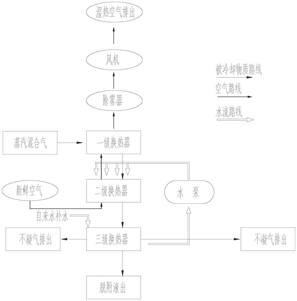
[0037] This embodiment provides a method for cooling and condensing steam based on the steam condensation and heat dissipation integrated equipment in Embodiment 1. The steam enters from one end of the heat exchange tube 5 in the primary heat exchange zone 2, and passes through the primary stage in turn. The heat exchange zone 2 is cooled once, the secondary heat exchange zone 3 is cooled twice, and the third heat exchange zone 4 is cooled three times. It is used to spray and lower the temperature of the material in the heat exchange tube 5 in the secondary heat exchange area 3; The contents are cooled.

[0038] Wherein, when the temperature is lowered once, the air flows from bottom to top to cool the material in the heat exchange tube 5, and the temperature of the material in the heat exchange tube 5 is lowered by using air as a medium; Up-down flow cools the material in the heat exchange tube 5, and uses liquid and air as the medium to reduce the temperature of the materia...


PUM


Abstract

The invention discloses a steam condensation method which comprises the following steps: steam enters from one end of a heat exchange pipe in a first-stage heat exchange area, sequentially passes through the first-stage heat exchange area for primary cooling, the second-stage heat exchange area for secondary cooling and the third-stage heat exchange area for third cooling, and then is discharged from one end of a heat exchange pipe in the third-stage heat exchange area; the spraying pipeline is used for spraying and cooling substances in the heat exchange pipe in the second-stage heat exchange area; the air inlet area is used for feeding air so as to cool substances in the heat exchange tubes in the first-stage heat exchange area and the second-stage heat exchange area; the first cooling is to reduce the temperature of substances in the heat exchange tube by taking air as a medium, the second cooling is to reduce the temperature of the substances in the heat exchange tube by taking liquid and air as media, and the third cooling is to reduce the temperature of the substances in the heat exchange tube by taking liquid as a medium. According to the steam condensation method, intermediate conversion loss is reduced, and the heat exchange efficiency is higher; and the air exhaust temperature of heat exchange is increased by utilizing self heat, so that the white smoke removal effect is achieved.

Description

technical field [0001] The invention belongs to the technical field of waste gas treatment, and in particular relates to a method for desorption steam condensation and heat dissipation. Background technique [0002] Existing waste gas recovery equipment such as toluene, after the activated carbon is desorbed by steam, the desorption liquid is connected to the traditional shell and tube condenser, and the temperature is lowered through the condenser. The refrigerant is cooling circulating water, which needs to be specially equipped with a cooling tower, using circulating water as the refrigerant Cool the high temperature desorption steam. Cool the desorbed vapor from gaseous state to liquid at about 40°C. [0003] Problems in the existing technology: 1. Below zero temperature in winter, the water freezes and cannot be used; 2. The cooling circulation water pipe freezes and cracks often occurs below zero temperature in winter; 3. The filling of the cooling tower is not resist...

Claims


Application Information

Patent Timeline
Patent Type & Authority Applications(China)
IPC IPC(8): B01D5/00B01D53/00B01D53/26
Inventor 尹东海周洋杨高建王豪杰
Owner 苏州赢众环保有限公司
Why Eureka
Try Eureka