Machine tool rotary table protection device and numerical control gear hobbing machine

A protection device and turntable technology, which is applied in the direction of gear cutting machine, gear tooth manufacturing device, gear teeth, etc., can solve the problems of eccentricity, chip removal, protective installation, etc., and achieve the effect of improving the fault tolerance rate and solving the problem of eccentricity

Pending Publication Date: 2022-04-12
秦川集团(西安)技术研究院有限公司
View PDF16 Cites 0 Cited by
  • Summary
  • Abstract
  • Description
  • Claims
  • Application Information

AI Technical Summary

Problems solved by technology

[0004] In view of this, the present invention mainly solves the problem of chip removal in the protection area of ​​the turntable and the problem of eccentricity of the protection installation, and improves the machining accuracy of the machine tool

Method used


Image

  • Machine tool rotary table protection device and numerical control gear hobbing machine
  • Machine tool rotary table protection device and numerical control gear hobbing machine
  • Machine tool rotary table protection device and numerical control gear hobbing machine

Examples


Embodiment 1

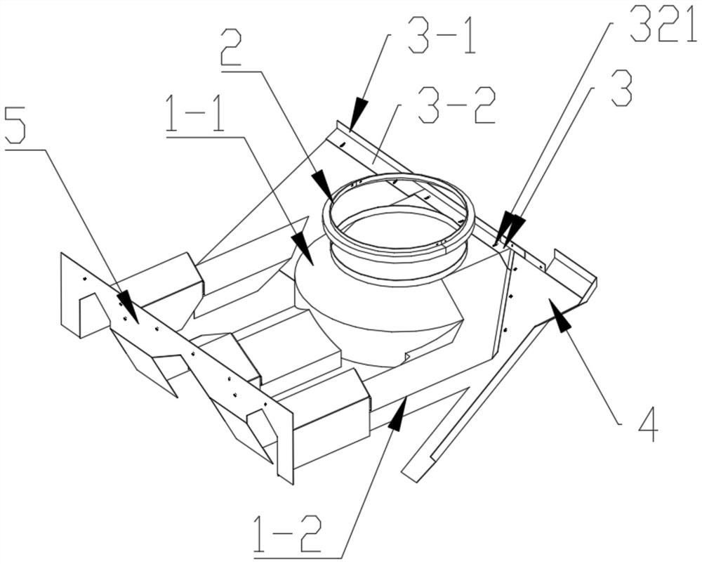
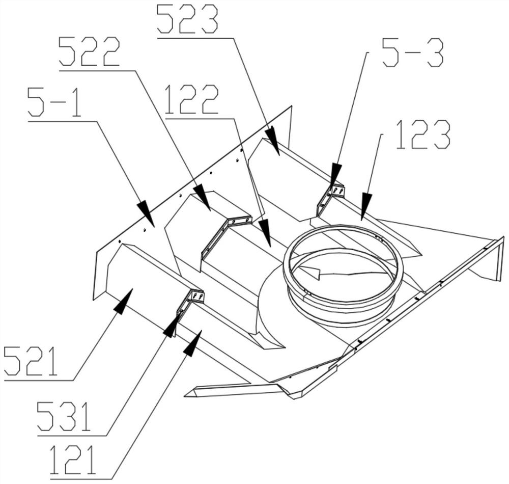
[0035] Such as Figure 1-2 As shown, a machine tool turntable protection device includes a turntable protective cover 1, a turntable support 2, a small column connecting plate 3 and a large column scraping plate structure 5, and the turntable protective cover 1 is provided with a circular arc for installing the turntable 10 The turntable bracket 2 on the surface, one end of the turntable protective cover 1 is fixedly connected with the small column connecting plate 3 and the other end is movably connected with the large column scraping plate structure 5, and the large column scraping plate structure 5 is used for scraping Turntable protective cover 1 is covered with iron filings.

[0036] On this basis, one side of the turntable protective cover 1 is also provided with a chip removal plate 4, one side of the chip removal plate 4 is connected to one side of the turntable protective cover 1 and the other side of the chip removal plate 4 is connected to the small The column conn...

Embodiment 2

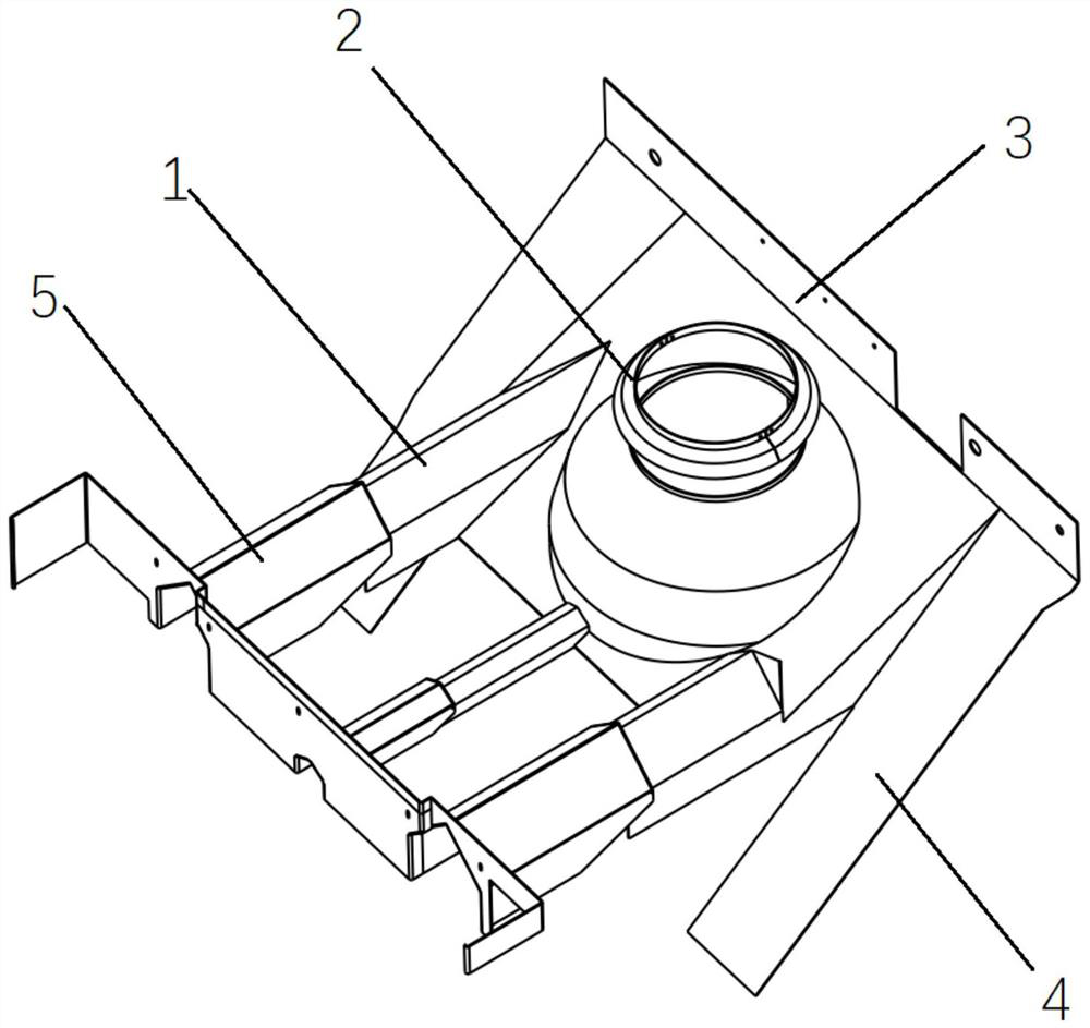
[0057] On the basis of Example 1, such as image 3 As shown, the turntable bracket 2 is in the shape of a top hat with the center of the turntable 10 as the center, the arc surface on which the turntable 10 can be installed as the inner circle radius, and the distance greater than the turntable 10 radius and not interfering with other components as the radius. The structure is installed on the arc surface of the turntable 10 by screws.

[0058] The purpose of this structure is to prevent iron filings from entering the interior of the turntable 10 from the gap existing at the connection between the arc surface of the turntable protective cover 1 and the turntable 10 .

Embodiment 3

[0060] On the basis of Embodiment 1 or 2, the protective device for the turntable of the machine tool is made of metal sheet metal materials, not limited to stainless steel and stainless iron materials.

[0061] The diameter of the circle in the turntable protective cover 1 is relatively large, so the problem of eccentricity will not occur.


PUM


Abstract

The invention relates to a machine tool rotary table protection device and a numerical control gear hobbing machine, and the machine tool rotary table protection device comprises a rotary table protection cover, a rotary table support, a small stand column connecting plate and a large stand column chip scraping plate structure, one end of the rotary table protective cover is fixedly connected with the small stand column connecting plate, and the other end of the rotary table protective cover is movably connected with the large stand column scrap scraping plate structure. The large stand column scrap scraping plate structure is used for scraping scrap iron on the rotary table protective cover. The error-tolerant rate between the protection plates is increased, the problem of eccentricity caused by rotary table protection installation errors can be effectively solved, cutting scrap iron is promoted to be rapidly discharged into the scrap discharging groove, and then the influence of thermal stress generated by high-temperature scrap iron on the machining precision of a machine tool is eliminated.

Description

technical field [0001] The invention relates to the technical field of numerical control machining, in particular to a protective device for a turntable of a machine tool and a numerical control gear hobbing machine. Background technique [0002] The main internal protection of the gear hobbing machine includes turntable protection, small column protection and tool holder protection. The turntable protection can protect the turntable and the parts on the turntable from being scratched by the processed iron chips and quickly discharge the processed iron chips to the chip conveyor. role. [0003] In the prior art, some machine tools have no turntable protection, and some with protection only divide the machine tool processing area from the non-processing area, which cannot effectively solve the problem of iron filings accumulation during the machining process of the machine tool, and the thermal stress caused by the accumulation of high-temperature iron filings It can have a ...

Claims


Application Information

Patent Timeline
IPC IPC(8): B23F23/12B23Q11/00
CPCY02P70/10
Inventor 刘耀但鹏车亚肖徐少帅李瑞亮
Owner 秦川集团(西安)技术研究院有限公司
Why Eureka
Try Eureka