Chemical auxiliary force rheological polishing machining device for ceramic hemispheres
A hemispherical chemical and processing device technology, applied in the direction of grinding/polishing safety devices, metal processing equipment, grinding/polishing equipment, etc., can solve the problems of no noise reduction and dust suppression, excessive dust, strong noise, etc., and achieve convenience Effects of replacement and maintenance, improvement of applicability, and improvement of stability
- Summary
- Abstract
- Description
- Claims
- Application Information
AI Technical Summary
Problems solved by technology
Method used
Image
Examples
Embodiment 1
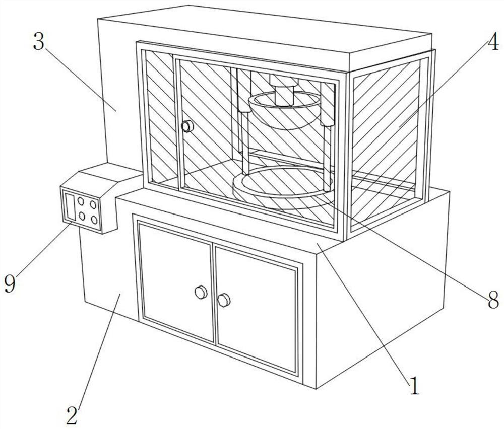
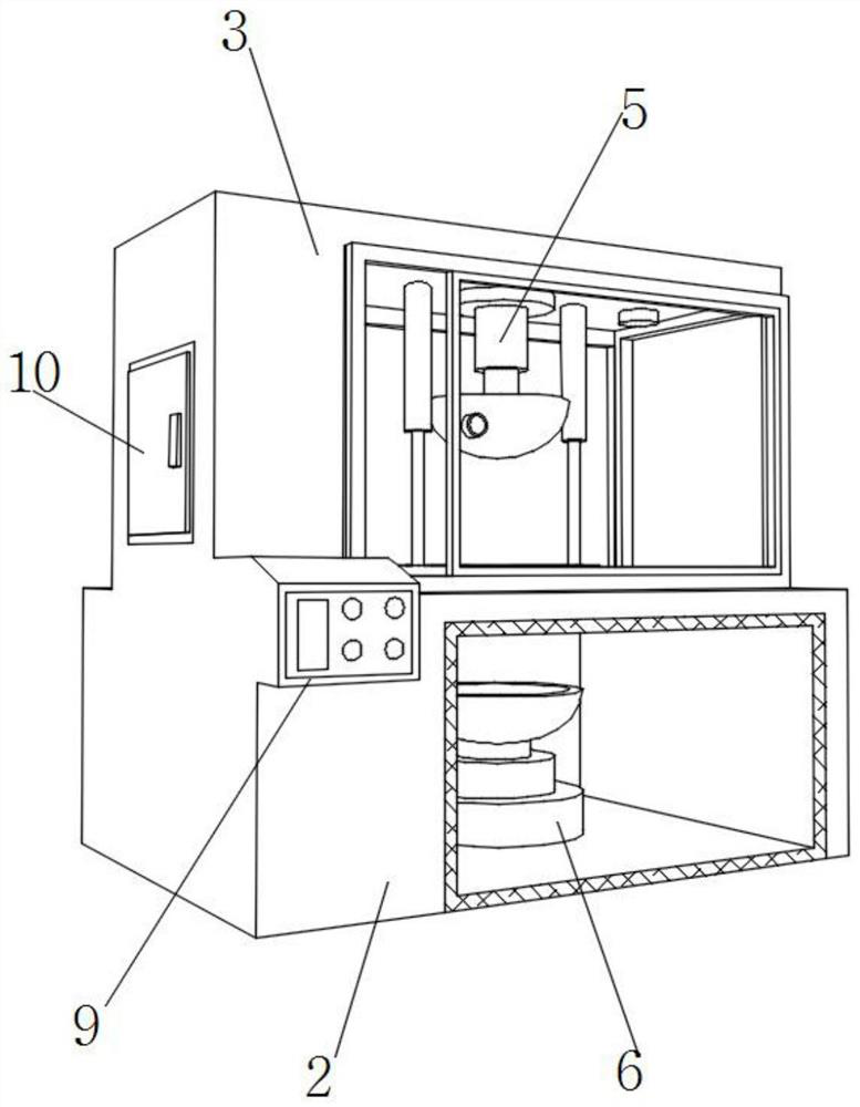
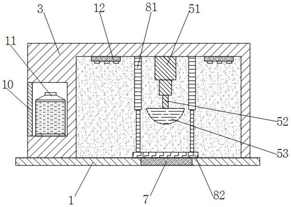
[0039] Such as Figure 1-7 As shown, the present invention provides a ceramic hemispherical chemically assisted rheological polishing device, comprising a polishing table 1, an internal polishing assembly 5 and an external polishing assembly 6, the bottom of the polishing table 1 is fixedly equipped with a base 2, and the bottom of the polishing table 1 The surface is provided with a through hole 7, the upper part of the through hole 7 is provided with a fixed assembly 8, the upper part of the grinding table 1 is fixedly installed with a protective shell 3, the inside of the protective shell 3 is provided with an internal polishing assembly 5, and the inside of the base 2 is provided with an external polishing assembly. Assembly 6, the internal polishing assembly 5 includes a first polishing element 51, an upper connecting sleeve 52 and a hemispherical inner grinding member 53, the lower part of the first polishing element 51 is fixedly equipped with an upper connecting sleeve ...
Embodiment 2
[0041] Such as Figure 1-7 As shown, on the basis of Embodiment 1, the present invention provides a technical solution: preferably, the inner thread of the upper connecting sleeve 52 is connected with a first connecting column 54, and the bottom of the first connecting column 54 is fixedly installed with a hemispherical inner Grinding part 53, the top of hemispherical inner grinding part 53 and the inside of upper connecting sleeve 52 are flexibly connected through the first connecting column 54 provided, and ceramic polishing workpiece 13 is placed on the inner side of fixed ring 82 when in use, ceramic polishing workpiece 13 The outer wall of the outer wall is in contact with the non-slip concave-convex surface layer 837 to increase the friction force, and the rubber filling layer 836 is deformed with the second arc-shaped elastic sheet 833 and the buffer column 834 to fix the ceramic polishing workpiece 13, and at the same time, it is combined with the elastic hemisphere 838...
Embodiment 3
[0043] Such as Figure 1-7 As shown, on the basis of Embodiment 2, the present invention provides a technical solution: preferably, the upper part of the fixed ring 82 is fixedly equipped with a support rod 81, and the support rod 81 is fixedly installed on the inner top surface of the protective shell 3, and the through hole The upper part of 7 is provided with fixed ring 82, and the front of protective casing 3 is fixedly installed with transparent window protective window 4, and the side of protective casing 3 is fixedly installed with side door body 10, and the inner wall of protective stability element 83 is provided with ceramic polishing workpiece 13, and protective casing There is a place on the left side of 3, one end of the water supply tank 11 is fixedly connected with a water pipe, and one end of the water pipe is fixedly connected with a dust-reducing atomizing nozzle 12, and the dust-reducing atomizing nozzle 12 is fixedly installed on the inner top surface of the...
PUM
 Abstract
Description
Claims
Application Information
 - R&D
- Intellectual Property
- Life Sciences
- Materials
- Tech Scout
- Unparalleled Data Quality
- Higher Quality Content
- 60% Fewer Hallucinations
Browse by: Latest US Patents, China's latest patents, Technical Efficacy Thesaurus, Application Domain, Technology Topic, Popular Technical Reports.
© 2025 PatSnap. All rights reserved.Legal|Privacy policy|Modern Slavery Act Transparency Statement|Sitemap|About US| Contact US: help@patsnap.com


