Automatic material taking and placing mechanism of engraving and milling machine

An automatic pick-and-place, engraving machine technology, applied to conveyor objects, furnaces, stone processing tools, etc., can solve problems such as low work efficiency, increased enterprise costs, and the inability of engraving machines to achieve streamlined operations, to improve work efficiency. Effect

Pending Publication Date: 2022-04-12
东莞市友鸿机电设备有限公司
View PDF0 Cites 2 Cited by
  • Summary
  • Abstract
  • Description
  • Claims
  • Application Information

AI Technical Summary

Problems solved by technology

[0003] The existing glass engraving machine needs to be equipped with a mechanical arm to automatically load and unload glass materials, but due to the high cost of the robotic arm, this undoubtedly increases the cost of the enterprise. Every time after finishing t...

Method used


Image

  • Automatic material taking and placing mechanism of engraving and milling machine
  • Automatic material taking and placing mechanism of engraving and milling machine
  • Automatic material taking and placing mechanism of engraving and milling machine

Examples


Embodiment 1

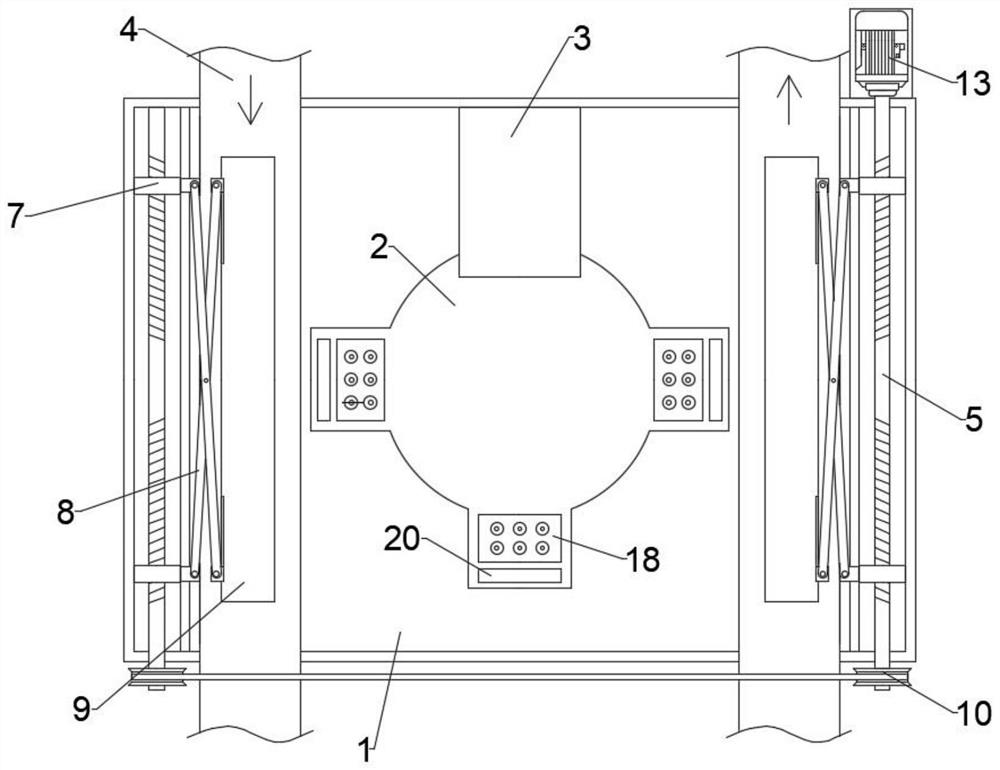
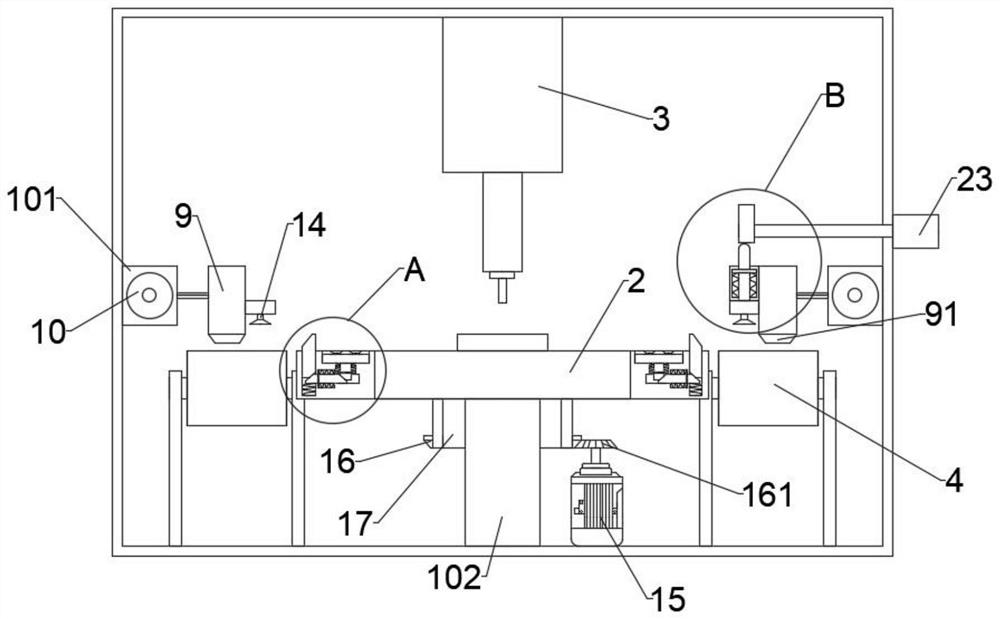
[0023] Such as Figure 1-3 As shown, the automatic loading and unloading mechanism of a fine carving machine proposed by the present invention includes a box body 1, the box body 1 is provided with an inner cavity, and the top cavity wall of the box body 1 is provided with an engraving and milling mechanism 3, and the left and right sides of the inner cavity Both parts are provided with a conveying mechanism 4 for conveying workpieces, the walls of the left and right ends of the inner cavity are equipped with auxiliary feeding mechanisms, the lower part of the inner cavity is provided with a rotating column 102, and the top of the rotating column 102 is provided with a processing turntable 2, The bottom wall of the processing turntable 2 is provided with a hollow sleeve 17, and the outer end of the hollow sleeve 17 is provided with a bevel gear ring 16. The bottom cavity wall of the inner cavity is detachably provided with a second motor 15, and the top of the second motor 15 i...

Embodiment 2

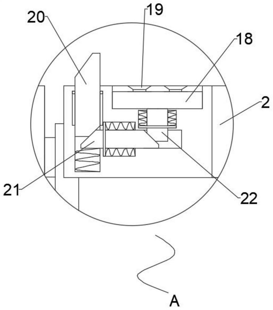
[0026] Such as Figure 2-5 As shown, the automatic loading and unloading mechanism of a fine carving machine proposed by the present invention, compared with the first embodiment, this embodiment also includes a limit mechanism including a positioning plate 18, a suction cup group 19 and a first tilting member 20, The top of the processing turntable 2 is provided with a cross-shaped rectangular groove, and a positioning plate 18 is embedded in the rectangular groove. The top of the positioning plate 18 is provided with a suction cup group 19, and the processing turntable 2 is provided with a first rectangular cavity below the rectangular groove. The second spring is evenly installed in the first rectangular cavity, and the second inclined part 22 is arranged, and the top of the second inclined part 22 is connected with the positioning plate 18, and the second rectangular cavity is arranged below the first rectangular cavity, and the second rectangular A third spring is evenly ...


PUM


Abstract

The invention relates to the technical field of glass engraving and milling machines, in particular to an automatic material taking and placing mechanism of an engraving and milling machine. According to the technical scheme, a box body is arranged, an inner cavity is formed in the box body, conveying mechanisms used for conveying workpieces are arranged on the left portion and the right portion of the inner cavity correspondingly, auxiliary feeding mechanisms are arranged on the cavity walls of the left end and the right end of the inner cavity correspondingly, a rotating column is arranged on the lower portion of the inner cavity, and a machining rotating disc is rotationally arranged on the top of the rotating column; a hollow sleeve is arranged on the bottom wall of the machining rotary disc, a bevel gear ring is arranged at the outer end of the hollow sleeve, and limiting mechanisms used for positioning workpieces are evenly arranged on the machining rotary disc. Through cooperation of the machining rotating disc, the conveying mechanism, the bidirectional lead screw, the suction cup mechanism, the connecting rod, the bevel gear, the bevel gear ring, the positioning plate, the cam and the abutting rod, the engraving and milling machine can conduct feeding and discharging at the same time through the simple structure, shutdown for material replacement is not needed, material taking or discharging is conducted through the conveying mechanism, and the production efficiency is improved. And the working efficiency of the engraving and milling machine is effectively improved.

Description

technical field [0001] The invention relates to the technical field of glass engraving machines, in particular to an automatic feeding and discharging mechanism of a fine engraving machine. Background technique [0002] Glass engraving machine is a kind of CNC machine tool, also known as: glass engraving machine, glass punching machine, glass edging machine, special-shaped glass cutting machine, glass slotting machine, precision glass forming machine. The concept was first proposed and realized by Shenzhen Ocean CNC. The glass engraving machine is mainly used in the fine processing and special-shaped cutting of various ultra-thin glass, and the technology is very mature. Due to the development and demand of the electronic consumer market in the future, more digital electronic display screens use glass as display screens or touch screens, and the market for glass engraving machines is also growing. [0003] The existing glass engraving machine needs to be equipped with a mec...

Claims


Application Information

Patent Timeline
IPC IPC(8): B28D1/22B28D1/30B28D7/04B28D7/00B65G47/91B65G49/06
Inventor 廖建明曾叶明曾水清李明明
Owner 东莞市友鸿机电设备有限公司
Why Eureka
Try Eureka