Vehicle-mounted solar charging pile

A technology of charging piles and solar energy, applied in electric vehicle charging technology, charging stations, vehicle energy storage, etc., can solve the problem of no place for charging, and achieve the effect of improving efficiency

Pending Publication Date: 2022-04-12
李龙勃
View PDF0 Cites 0 Cited by
  • Summary
  • Abstract
  • Description
  • Claims
  • Application Information

AI Technical Summary

Problems solved by technology

[0005] The technical problem to be solved in the present invention: by combining solar power generation and charging piles, emergency power supply is provided for automobiles, so as to solve the problem that automobiles have no place to charge in emergency situations

Method used


Image

  • Vehicle-mounted solar charging pile
  • Vehicle-mounted solar charging pile
  • Vehicle-mounted solar charging pile

Examples


specific Embodiment approach

[0043] As a specific embodiment of the present invention, the transmission assembly 10 includes:

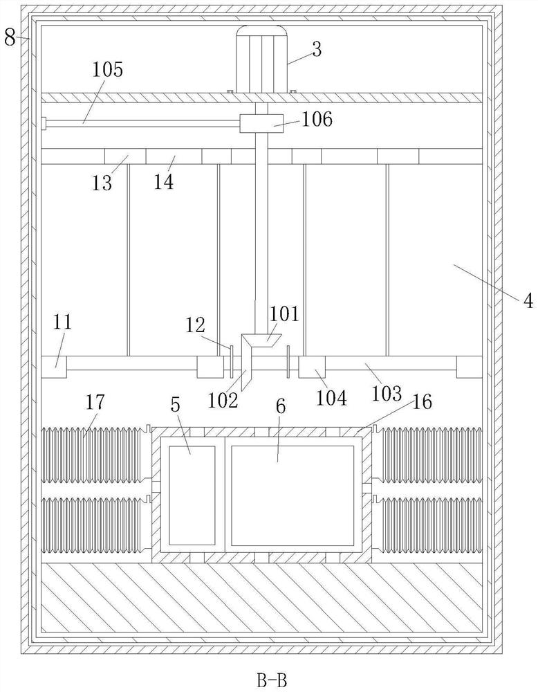
[0044] The first bevel gear 101: the first bevel gear 101 is fixedly connected with the output shaft of the motor 3;

[0045] Second bevel gear 102: the second bevel gear 102 meshes with the first bevel gear 101;

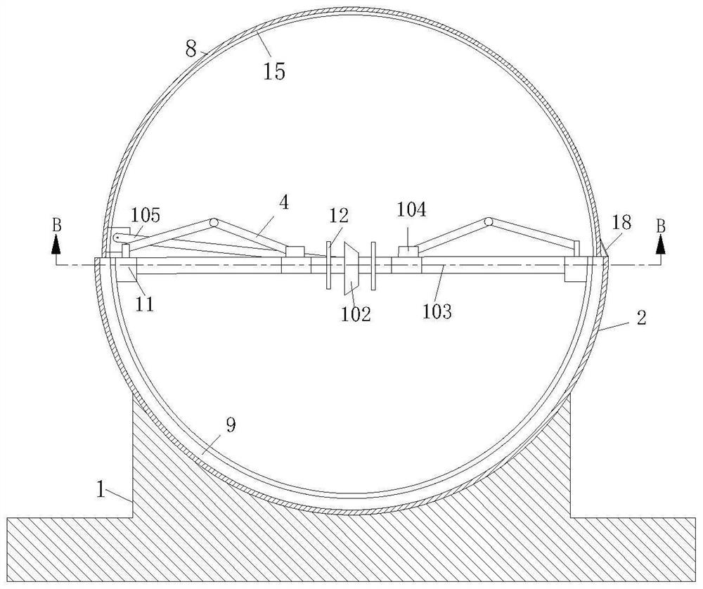
[0046]Screw rod 103: The screw rod 103 is located inside the pile body 1 and close to the battery 6, the middle part of the outer surface of the screw rod 103 is fixedly connected with the second bevel gear 102, and the two ends of the screw rod 103 are threaded The direction of rotation is opposite, and the outer surfaces of both sides of the screw rod 103 are threadedly connected with sliders 104. The number of the sliders 104 is two. One side of the sliders 104 is hinged with a solar panel 4, and one of the two solar panels 4 Interphase hinge;

[0047] Connecting rod 105: The connecting rod 105 is fixedly connected to the inner wall of the second protective cover ...

Embodiment approach

[0053] As a specific embodiment of the present invention, the solar panel 4 is a double-sided solar panel 4, and the side of the solar panel 4 close to the motor 3 is provided with a roller 13, and the outer surface of the roller 13 rolls with the slide rail 14 connect.

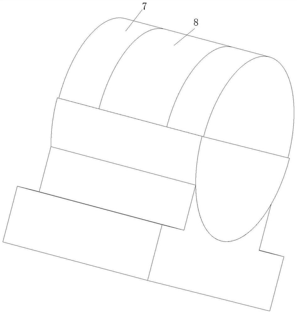
[0054] As a specific embodiment of the present invention, a flexible reflector 15 is provided inside the pile body 1 and on the surface of the second protective cover 8 .

[0055] In order to promote the working efficiency of the solar panel 4, the solar panel 4 used in the present invention is a double-sided solar panel 4, which increases the area of ​​the solar panel 4, and absorbs light energy on the inner wall of the second protective cover 8 and the pile body 1 to the greatest extent. The inner wall is provided with a flexible reflector 15, so the second protective cover 8 and the solar panel 4 can be adjusted along with the direct sunlight of the sun at any time of the day to improve the performance of ...


PUM


Abstract

The invention belongs to the technical field of charging piles, and particularly relates to a vehicle-mounted solar charging pile. Comprising a pile body, a base, a motor, a solar panel and a storage battery, and further comprises a transmission assembly and two first protective covers, the transmission assembly is located in the pile body and close to the motor, the first protective covers are fixedly connected with the pile body, and the first protective covers are semicircular; the second protective cover is located between the two first protective covers, and the second protective cover is semicircular; solar power generation and the charging pile are combined, the transmission assembly outputs power to adjust the solar panel to promote the solar panel to absorb light energy so as to charge the storage battery, and the second protective cover is adjusted to achieve the purpose of protecting the solar panel from being damaged.

Description

technical field [0001] The invention belongs to the technical field of charging piles, in particular to a vehicle-mounted solar charging pile. Background technique [0002] With the development of economy and technology and the improvement of living conditions, traveling by car has become more and more people's first choice. Trams are more and more popular due to their energy saving, environmental protection and low noise. However, the biggest concern of trams is the problem of power supply. [0003] At present, the charging piles on the market are large in size and occupy a large area. They are all installed in fixed positions, which greatly limits the range of charging. However, as trams become more and more popular, the facilities of charging piles are not very sound. There are even no charging piles in many areas, which leads to the fact that trams cannot be charged in many cases. [0004] In view of this, in order to overcome the above-mentioned technical problems, the...

Claims


Application Information

Patent Timeline
Patent Type & Authority Applications(China)
IPC IPC(8): B60L53/31B60L53/51B60L53/53H02S20/30H02S40/10H02S40/38
CPCY02E10/50Y02E70/30Y02T10/70Y02T10/7072Y02T90/12
Inventor 李龙勃刘晨旭
Owner 李龙勃
Why Eureka
Try Eureka