
Electronic drive-by-wire booster control system

A control system and booster technology, applied in the directions of brakes, brake transmissions, transportation and packaging, etc., can solve the problems of insufficient brake booster, inaccurate data, insufficient motor efficiency, etc., to avoid control lag and improve control accuracy. Effect

Inactive Publication Date: 2022-04-12
WANXIANGQIANCHAO CO LTD
View PDF6 Cites 2 Cited by
  • Summary
  • Abstract
  • Description
  • Claims
  • Application Information

AI Technical Summary

Problems solved by technology

[0002] On the one hand, the existing electronic power-by-wire system lacks a hydraulic auxiliary control module. When the vehicle body is heavy, especially when the full load is larger than the large tonnage, because it needs to meet the 200ms braking pressure of the large tonnage vehicle to reach the pressure building requirement of 10MPa, it is necessary to use a Larger brake calipers require fluid, and the existing electronic power assist system without a hydraulic auxiliary module cannot meet the pressure building requirements due to reasons such as limited pedal travel or insufficient motor efficiency, which affects the braking deceleration of the vehicle and leads to brake boosting Insufficient, on the other hand, there is no pressure closed-loop control for pressure sensing. The existing technical solutions lack hydraulic adjustment modules and no pressure sensors to sense pressure in real time. The pressure of each part of the system is estimated by a virtual vehicle pressure model algorithm. Potential danger of inaccurate or lagging data

Method used


Image

  • Electronic drive-by-wire booster control system
  • Electronic drive-by-wire booster control system

Examples


Embodiment 1

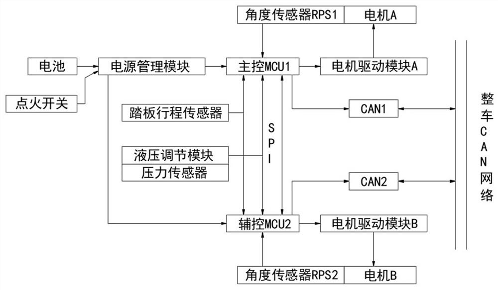
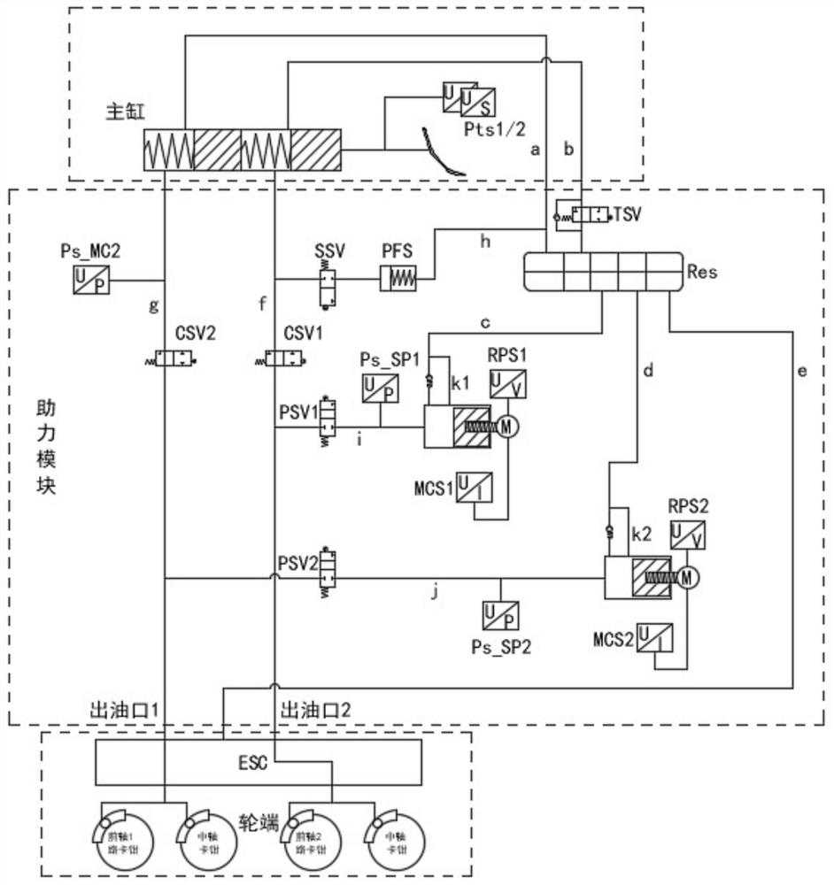
[0025] see figure 1 and figure 2 , the present invention provides a technical solution: an electronic drive-by-wire booster control system, including an ECU module, a pedal stroke sensor module, a motor module, a hydraulic adjustment module, and a pressure sensor module. The ECU module includes a main control MCU1, an auxiliary control MCU2, CAN1 and CAN2, CAN1 and CAN2 are used for signal interaction with the CAN network of the vehicle. The motor module includes a motor, a motor drive module and a motor angle sensor module. The motor includes motor A and motor B. The motor drive module includes motor drive module A and motor The drive module B, the motor angle sensor module includes angle sensors RPS1 and RPS2, the motor A sub-pump A builds the pressure, the motor B controls the sub-pump B builds the pressure, the main control MCU1 controls the motor A, the auxiliary control MCU2 controls the motor B, and the hydraulic adjustment module includes Master cylinder, booster mod...


PUM


Abstract

The invention discloses an electronic drive-by-wire booster control system which comprises an ECU module, a pedal travel sensor module, a motor module, a hydraulic adjusting module and a pressure sensor module, the ECU module comprises a main control MCU1, an auxiliary control MCU2, a CAN1 and a CAN2, and the motor module comprises a motor, a motor driving module and a motor rotation angle sensor module. The hydraulic adjusting module comprises a main cylinder, a power assisting module and an ESC module. According to the system, firstly, the braking deceleration requirement of a large-tonnage vehicle is met, independent pressurization can be independently achieved, and active pressurization can also be achieved through cooperation with an ESC module, secondly, three pressure sensors are arranged and distributed at oil outlets of a main cylinder and two branch pumps of the hydraulic adjusting module, the pressure of the main cylinder and the pressure of the branch pumps are collected, and the pressure of the main cylinder and the pressure of the branch pumps are calculated. Pressure is fed back in real time, the defects of a vehicle pressure model are effectively overcome, control lag is avoided, and the control precision is improved.

Description

technical field [0001] The invention relates to the technical field of electronic drive-by-wire booster control systems, in particular to an electronic drive-by-wire booster control system. Background technique [0002] On the one hand, the existing electronic power-by-wire system lacks a hydraulic auxiliary control module. When the vehicle body is heavy, especially when the full load is larger than the large tonnage, because it needs to meet the 200ms braking pressure of the large tonnage vehicle to reach the pressure building requirement of 10MPa, it is necessary to use a Larger brake calipers require fluid, and the existing electronic power assist system without hydraulic auxiliary modules cannot meet the pressure building requirements due to reasons such as limited pedal travel or insufficient motor efficiency, which affects the braking deceleration of the vehicle and leads to brake boosting Insufficient, on the other hand, there is no pressure closed-loop control for pr...

Claims


Application Information

Patent Timeline
Patent Type & Authority Applications(China)
IPC IPC(8): B60T13/74
Inventor 陈颖任博屈亮亮郑美云林国贤张霞
Owner WANXIANGQIANCHAO CO LTD
Learn More