Buoyancy box type flap valve and automatic opening and closing method thereof

A floating box and door panel technology, applied in marine engineering, construction, barrage/weir, etc., can solve the problem that the gate cannot be automatic, and achieve the effect of prolonging the service life, reducing noise and prolonging the overall service life.

Pending Publication Date: 2022-04-12
HEBEI RES INST OF INVESTIGATION & DESIGN OF WATER CONSERVANCY & HYDROPOWER
View PDF2 Cites 0 Cited by
  • Summary
  • Abstract
  • Description
  • Claims
  • Application Information

AI Technical Summary

Problems solved by technology

However, the opening and closing of the gate cannot be realized automatically, and manual operation of the lifting device is required for control

Method used


Image

  • Buoyancy box type flap valve and automatic opening and closing method thereof
  • Buoyancy box type flap valve and automatic opening and closing method thereof
  • Buoyancy box type flap valve and automatic opening and closing method thereof

Examples


Embodiment 1

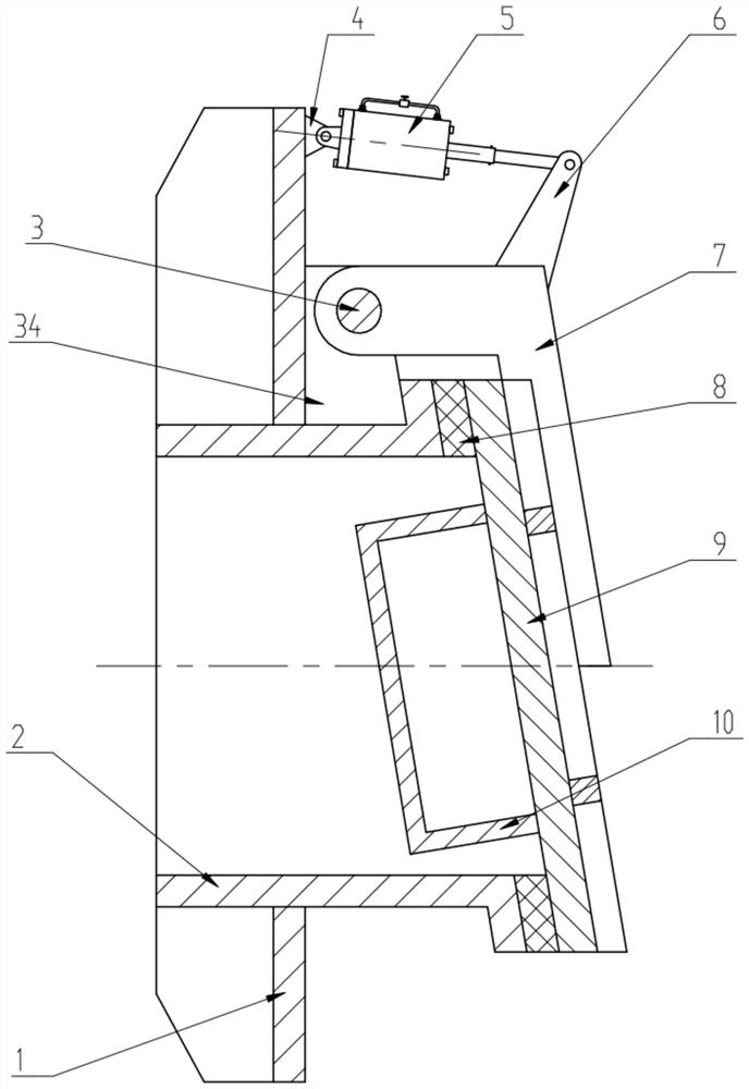
[0033] Such as figure 1 As shown, a buoyant box-type flap door and its self-opening and closing method include a vertical rectangular mounting plate 1, a cylindrical overflow pipe 2 that is fixed and fixed on the mounting plate 1 through a vertical Door panel 9 at outlet of flow tube 2. The door panel 9 and the flow pipe 2 are sealed and matched by the gasket 8 embedded in the right end surface of the flow pipe 2. The inside of the door panel 9 is welded with a closed circular box 10, and the outside of the door panel 9 is provided with 7 Glyph swing arm 7, the outer side of the door panel 9 is welded with reinforcing ribs, the lower end of the swing arm 7 is welded on the reinforcing ribs, and the left end of the swing arm 7 is hinged with the first lug 34 welded on the mounting plate 1, so The installation plate 1 is also provided with a slow closing device for slowly closing the door panel 9 , and the slow closing device is arranged above the overflow pipe 2 .
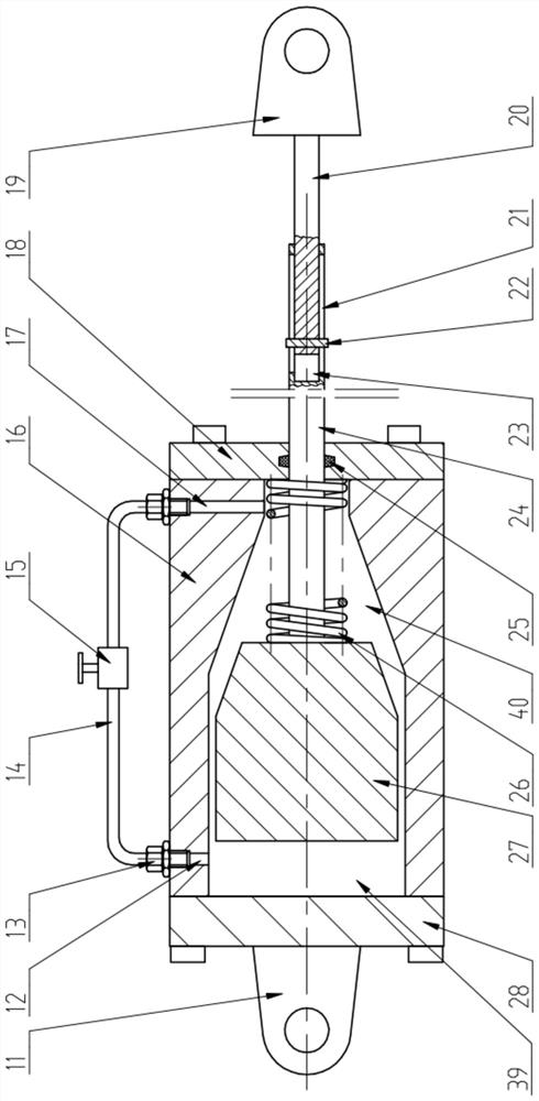
[0034] Su...

Embodiment 2

[0046] The difference between this embodiment and embodiment 1 is:

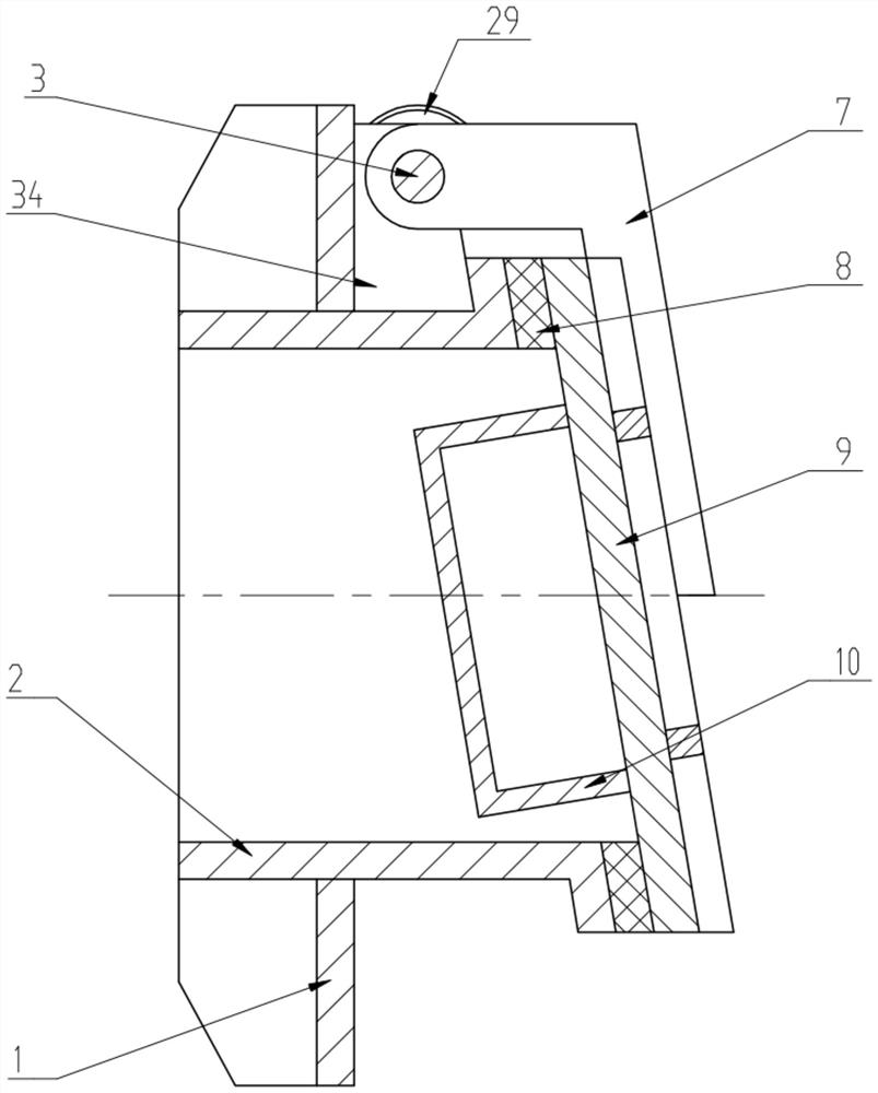
[0047] Such as image 3 The slow closing device shown is a disc damper 29 fixedly connected to the mounting plate 1, the shell of the disc damper 29 is fixedly connected to the mounting plate 1, and the upper left end of the swing arm 7 is fixedly provided with a hinge shaft 3. The hinge shaft 3 is rotatably connected to the first lug 34 .

[0048] Such as Figure 4 As shown, the hinge shaft 3 is provided with a disc-shaped first toothed plate 31, the first toothed plate 31 and the hinge shaft 3 are slidingly fitted, and the first toothed plate 31 and the hinge shaft 3 are connected by a sliding key . A disk-shaped second tooth plate 30 is provided on the right side of the first tooth plate 31 . The right side of the first tooth plate 31 has inclined first teeth 36 evenly distributed along the circumference, and the left side of the second tooth plate 30 has inclined second teeth 37 uniformly distributed ...

Embodiment 3

[0052] Such as Figure 5 Shown, the difference between this embodiment and embodiment 1 is:

[0053] The upper position of the door panel 9 is provided with a water injection screw plug 41 for injecting water into the box body 10 , and the lower position of the door panel 9 is provided with a water discharge screw plug 42 for releasing the water in the box body 10 .

[0054] Unscrew the water injection screw plug 41 to inject water into the casing 10, or unscrew the waterproof screw plug 42 to discharge the water in the casing 10, and adjust the water yield in the casing 10, thereby adjusting and increasing the downward force applied to the door panel 9, Thereby, the closing speed of the door panel 9 and the close force of the door panel 9 and the sealing gasket 8 are adjusted, so that the opening and closing of the door panel 9 can make the force adjustable.


PUM


Abstract

The invention discloses a buoyancy tank type flap valve and an automatic opening and closing method thereof. The buoyancy tank type flap valve comprises a vertical mounting plate, an overflowing pipe and a door plate, wherein the overflowing pipe transversely penetrates through the mounting plate and is fixedly arranged on the mounting plate, and the outlet of the overflowing pipe is covered with the door plate. The door plate is in sealing fit with the overflowing pipe, a closed box body is fixedly arranged on the inner side of the door plate, a swing arm is arranged on the outer side of the door plate, one end of the swing arm is fixedly connected with the door plate, the other end of the swing arm is hinged to the mounting plate, a slow closing device used for slowly closing the door plate is further arranged on the mounting plate, and the slow closing device is arranged above the overflowing pipe. The resistance when the door plate is opened is reduced, and when water flow passes through, the door plate can be burst open by means of self-flowing water pressure and buoyancy of the buoyancy box to achieve self-flowing drainage. And the river water is stopped by utilizing the pressure of the river water and the dead weight of the door plate after draining. Therefore, an opening and closing mechanism is not needed, manual operation is not needed, and the problems that when a traditional dike-penetrating culvert gate is opened and closed, manual operation is needed, time and labor are wasted, operation is inconvenient, and engineering investment is large are effectively solved.

Description

technical field [0001] The invention relates to the technical field of hydraulic facilities, in particular to a buoyant box-type flap door and its self-opening and closing method. Background technique [0002] The culvert is a drainage structure in the embankment, and the sluice is a kind of water retaining and drainage equipment installed at the end of the culvert and built on the embankment. In the flood season, it cooperates with the embankment of the river to play the role of controlling the water flow. [0003] At present, the general conventional dike-crossing culvert gates are provided with gates and opening and closing mechanisms. When the opening and closing mechanism drives the gate to close, it blocks the river water in the embankment, prevents the river water from flowing backward into the pipeline, and realizes the flood control function. After the opening and closing mechanism drives the gate to open, it can realize the drainage function in the flood season. ...

Claims


Application Information

Patent Timeline
Patent Type & Authority Applications(China)
IPC IPC(8): E02B7/20E02B7/52E02B8/00
Inventor 李红段宏宽唐海霞王丽娜
Owner HEBEI RES INST OF INVESTIGATION & DESIGN OF WATER CONSERVANCY & HYDROPOWER
Why Eureka
Try Eureka