Offshore wind generating set cooling system adopting heat pipe for cooling

A technology for wind turbines and cooling systems, applied in wind turbine combinations, wind turbines, wind power generation, etc., can solve the problems of demagnetization of the permanent magnets of the wind turbines, reduction of the service life and generation time of the generator, and increase of the temperature of the engine room. Short lifespan, simple and compact cabin structure, and improved heat dissipation efficiency

Pending Publication Date: 2022-04-12
HARBIN INST OF TECH +1
View PDF0 Cites 0 Cited by
  • Summary
  • Abstract
  • Description
  • Claims
  • Application Information

AI Technical Summary

Problems solved by technology

[0009] The purpose of the present invention is to solve the existing high-power wind power generators that easily cause the temperature of the cabin to rise, resulting in the demagnetization of the permanent magnet of the fan and the reduction of the service life and power generation time of the generator. Genset Cooling System

Method used


Image

  • Offshore wind generating set cooling system adopting heat pipe for cooling
  • Offshore wind generating set cooling system adopting heat pipe for cooling
  • Offshore wind generating set cooling system adopting heat pipe for cooling

Examples


specific Embodiment approach 1

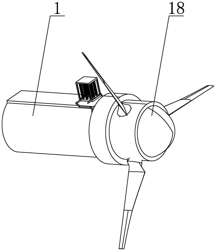
[0042] Specific implementation mode one: combine Figure 1 to Figure 8 This embodiment is described. In this embodiment, a cooling system for an offshore wind power generating set that adopts heat pipe cooling, the cooling system for an offshore wind generating set includes a generating set body, and the generating set body includes a cylindrical nacelle 1, a platform 2 and The direct-drive permanent magnet generator, the direct-drive permanent magnet generator includes the direct-drive permanent magnet generator stator 3, the cylinder cabin 1 is horizontally arranged, the platform 2 is horizontally arranged inside the cylinder cabin 1, and the platform 2 and The inner wall of the cylinder cabin 1 is fixedly connected, the direct-drive permanent magnet generator stator 3 is coaxially and fixedly installed on the front end of the cylinder cabin 1, and the stator 3 of the direct-drive permanent magnet generator is internally processed with a stator cooling circuit;

[0043] The ...

specific Embodiment approach 2

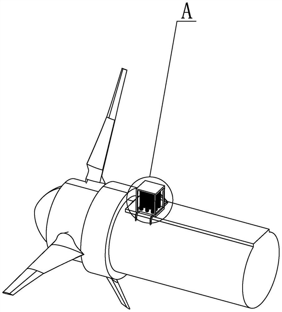
[0046] Specific implementation mode two: combination figure 1 and figure 2 To illustrate this embodiment, the top end of the cylindrical nacelle 1 of this embodiment is provided with a nacelle boss along the length direction, and the heat pipe radiator 4 is fixedly installed on the upper end surface of the nacelle boss. In this way, in order to increase the internal space of the cylindrical nacelle 1 , the heat pipe radiator 4 is installed above the cylindrical nacelle 1 . Other compositions and connections are the same as in the first embodiment.

specific Embodiment approach 3

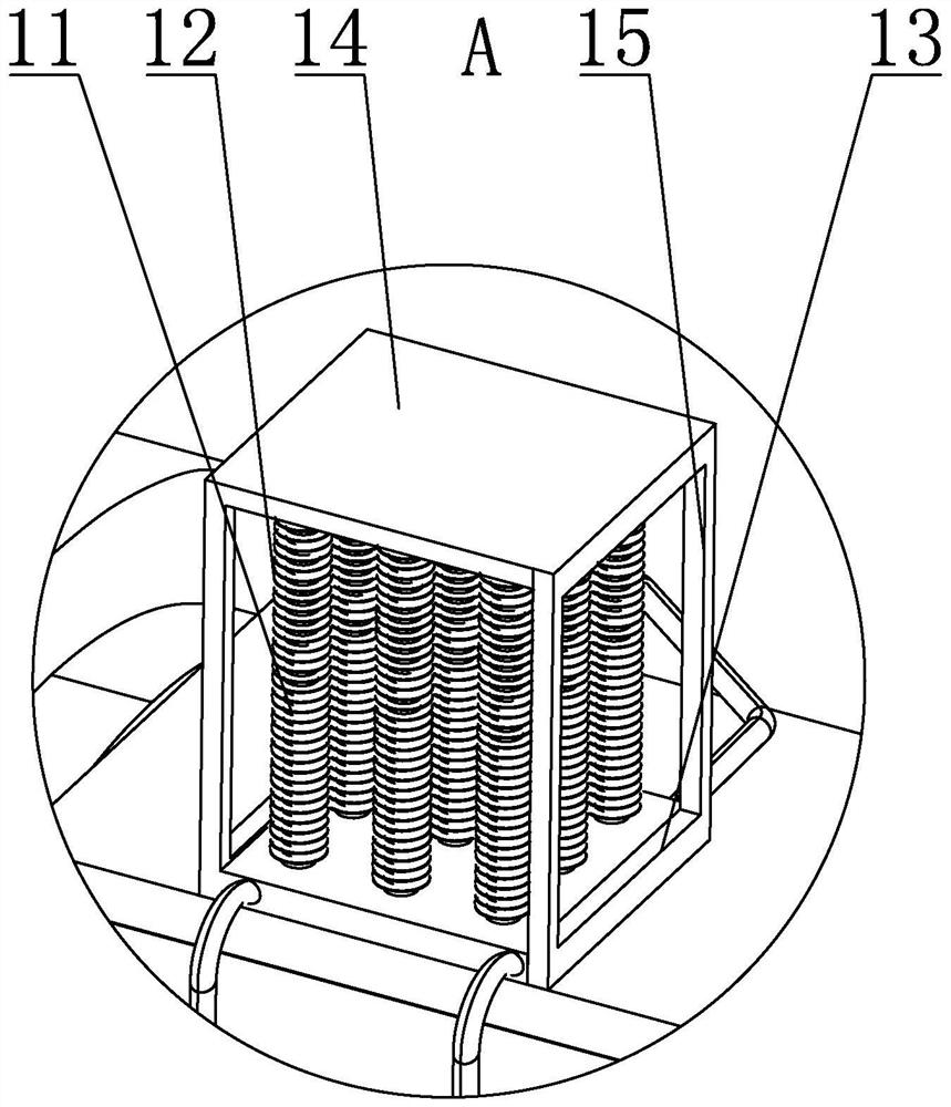
[0047] Specific implementation mode three: combination figure 2 and image 3 Describe this embodiment, the heat pipe radiator 4 of this embodiment includes a radiator body and a plurality of gravity heat pipes 11, a transition header is provided at the bottom of the radiator body, and a plurality of heat pipes connected to the transition header are processed on the upper end of the transition header. hole, a plurality of gravity heat pipes 11 are vertically arranged above the radiator body, and the gravity heat pipes 11 are condensing section, heat insulation section and evaporation section from top to bottom, and the evaporation section of gravity heat pipe 11 is inserted into the transition main pipe through the heat pipe assembly hole , the gravity heat pipe 11 is sealed and connected with the transition header. In this way, in order to make the heat dissipation efficiency of the external heat pipe radiator 4 not affected by seasons and weather, the gravity heat pipe 11 i...


PUM


Abstract

The invention discloses an offshore wind generating set cooling system adopting a heat pipe for cooling, and relates to the technical field of offshore wind generators. The problems that according to an existing high-power wind driven generator, the temperature of a cabin is likely to rise, a permanent magnet of a fan is demagnetized, and the service life and power generation time of the generator are shortened are solved. A cooling system of a barrel cabin is integrally designed, and a heat pipe type radiator is adopted for cooling for a high-power wind generating set with the power being 10 MW or above. An independent first cooling loop is formed by a direct-drive permanent magnet generator stator, a generator cooling liquid pump, a cooling liquid storage tank, a heat pipe type radiator and a connecting pipe. The control cabinet cooling liquid pump, the control cabinet heat exchanger, the control cabinet, the cooling liquid storage tank, the heat pipe type radiator and the connecting pipe form another independent second cooling loop, and finally heat is cooled in a centralized mode through the heat pipe type radiator. The system is used for carrying out centralized cooling on the direct-driven permanent magnet generator and the control cabinet of the offshore wind generating set.

Description

technical field [0001] The invention relates to the technical field of offshore wind power generators, in particular to a cooling system for offshore wind power generators that adopts heat pipe cooling. Background technique [0002] With the decrease of fossil energy, wind energy, as a conversion form of solar energy, has been paid more and more attention by people. However, in some areas of China, due to geographical location and electrical limitations of wind power generation, and the power system near wind farms is too weak to maintain the power fluctuations caused by wind power generation, it is impossible to introduce a large amount of land wind power. In order to solve the power demand in difficult areas, offshore wind farms have begun to be researched and developed. Since the monsoon is active throughout the year in our country, offshore wind energy resources are very rich, and the annual average wind speed in offshore waters is basically maintained between 7.0 and 8...

Claims


Application Information

Patent Timeline
Patent Type & Authority Applications(China)
IPC IPC(8): F03D80/60F03D9/25F03D80/00
CPCY02E10/72Y02P80/10
Inventor 张振寰章林琪袁远关延江钟向勋
Owner HARBIN INST OF TECH
Why Eureka
Try Eureka