Energy-saving spring type hydraulic power machine

A spring type, power machine technology, applied in the direction of brake actuators, fluid pressure actuation devices, fluid pressure actuation system components, etc., can solve safety accidents, safety hazards and other problems, to reduce consumption, smooth hydraulic flow, save energy effect

Pending Publication Date: 2022-04-12
NANTONG HANGTAI MARINE MACHINERY CO LTD
View PDF0 Cites 0 Cited by
  • Summary
  • Abstract
  • Description
  • Claims
  • Application Information

AI Technical Summary

Problems solved by technology

[0007] The present invention provides an energy-saving spring-type hydraulic power machine, which has the beneficial effect of automatic braking and energy saving, and solves the certain potential safety hazards of external braking mentioned in the above background technology. If a mistake occurs during the operation, Problems that are likely to cause safety accidents

Method used


Image

  • Energy-saving spring type hydraulic power machine
  • Energy-saving spring type hydraulic power machine
  • Energy-saving spring type hydraulic power machine

Examples


Embodiment 1

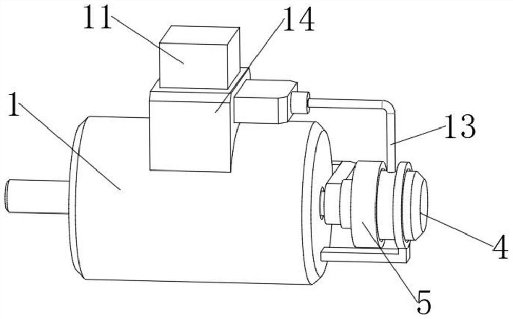
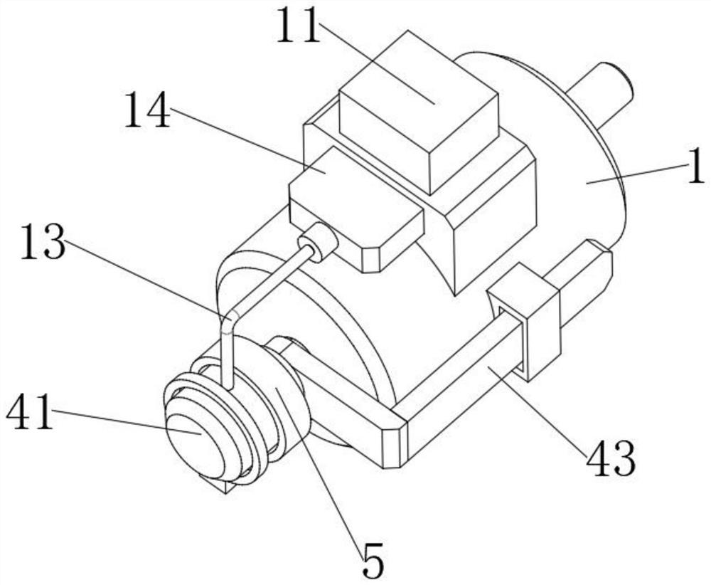
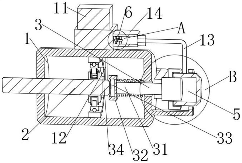
[0035] see Figure 1-3 , comprising a motor housing 1, the motor housing 1 is provided with a hydraulic shaft 2 for rotation, and the motor housing 1 is also provided with a braking mechanism 3, the braking mechanism 3 is used to stop the hydraulic shaft 2 from rotating;

[0036] The brake mechanism 3 includes a brake lever 31 slidably arranged on the motor housing 1. The brake lever 31 is provided with a groove 33, and the hydraulic shaft 2 is provided with a block 34 that is compatible with the groove 33. And the block 34 is slidably disposed in the groove 33 .

[0037] In this embodiment: in order to quickly stop the hydraulic shaft 2, a braking mechanism 3 is provided on the motor housing 1, and the braking mechanism 3 can accelerate the stopping of the hydraulic shaft 2, thereby reducing the consumption of hydraulic oil.

[0038] Stall: The brake lever 31 can be slid towards the direction close to the hydraulic shaft 2 through an external device, so that the block 34 on ...

Embodiment 2

[0041] This embodiment is an improvement made on the basis of Embodiment 1, please refer to Figure 1-3 , The brake lever 31 is also provided with a return spring 35 , and the brake lever 31 is elastically connected to the motor housing 1 through the return spring 35 .

[0042] In this embodiment: in order to reset the brake lever 31, a return spring 35 is provided on the brake lever 31. When the brake lever 31 loses its external limit, the return spring 35 will produce a reverse force on the brake lever 31. Push force, so that the brake lever 31 slides towards the direction close to the motor housing 1, and then the brake lever 31 is far away from the hydraulic shaft 2, so that the hydraulic shaft 2 can rotate again.

Embodiment 3

[0044] This embodiment is an improvement made on the basis of Embodiment 2, please refer to Figure 1-3 , The motor housing 1 is provided with a protrusion 32 that is compatible with the brake lever 31 , and the brake lever 31 is slidably disposed in the protrusion 32 .

[0045] In this embodiment: in order to support the brake lever 31, prevent the brake lever 31 from falling off when sliding on the motor housing 1, thus causing the brake lever 31 to be stuck between the hydraulic shaft 2, resulting in hydraulic pressure The rotating shaft 2 cannot resume rotation, and the motor housing 1 is also provided with a bump 32, and the brake lever 31 is slidably arranged in the bump 32, and the sliding of the brake lever 31 can be supported and limited by the bump 32 , thereby preventing the brake lever 31 from falling off from the motor housing 1 during the sliding process.


PUM


Abstract

The invention relates to the technical field of power machines, and discloses an energy-saving spring type hydraulic power machine which comprises a motor shell, a hydraulic rotating shaft is rotationally arranged in the motor shell, a brake mechanism is further arranged in the motor shell, and the brake mechanism is used for stopping rotation of the hydraulic rotating shaft. The braking mechanism is arranged on the motor shell, rotation stopping of the hydraulic rotating shaft can be accelerated through the braking mechanism, so that consumption of hydraulic oil is reduced, the braking mechanism is driven by the hydraulic oil in the hydraulic bin, the braking effect is achieved, an additional driving device does not need to be added, and the purpose of saving energy is achieved. And the phenomena of liquid overflow and backflow in the reversing valve body can be prevented through the adjusting mechanism, so that smooth flowing of hydraulic pressure in the rotating pipe is ensured.

Description

technical field [0001] The invention relates to the technical field of power machines, in particular to an energy-saving spring-type hydraulic power machine. Background technique [0002] A hydraulic power machine is a kind of hydraulic engine. A hydraulic engine refers to an engine that uses liquid as a working medium and uses the pressure energy of the liquid to transmit power. [0003] An engine is a machine that can convert other forms of energy into mechanical energy, including internal combustion engines (gasoline engines, etc.), external combustion engines (Stirling engines, steam engines, etc.), electric motors, etc. For example, internal combustion engines usually convert chemical energy into mechanical energy. The engine is not only applicable to the power generation device, but also refers to the whole machine including the power device (such as: gasoline engine, aero engine). The engine was first born in the UK, so the concept of the engine also comes from Engl...

Claims


Application Information

Patent Timeline
Patent Type & Authority Applications(China)
IPC IPC(8): F15B13/02F15B21/00F16D65/14F16D121/02
Inventor 钱刚
Owner NANTONG HANGTAI MARINE MACHINERY CO LTD
Why Eureka
Try Eureka