
Bearing assembly for wind driven generator

A technology for wind turbines and bearing components, which is applied in the direction of wind turbines, wind power generation, bearing components, etc., can solve the problems of inconvenient installation of shaft current insulation parts, difficulty in replacement, and high installation costs, and achieve convenient molding and effective layout. Avoid electric corrosion of bearings and facilitate processing and maintenance

Pending Publication Date: 2022-04-12
HUNAN CHONGDE IND TECH
View PDF0 Cites 0 Cited by
  • Summary
  • Abstract
  • Description
  • Claims
  • Application Information

AI Technical Summary

Problems solved by technology

During the operation of the wind turbine, due to balance, air gap, load, friction, wiring and other reasons, it is easy to generate a potential difference near the rolling bearing unit, and it is easy to cause electric corrosion to the rolling bearing raceway and rolling body in the rolling bearing unit, which will cause damage to the rolling bearing, resulting in Problems such as abnormal noise and excessive vibration affect the service life of rolling bearings; and the rolling bearings used in wind turbines are large-sized bearings, which are difficult and costly to replace when damaged
Especially with the increasing power requirements of semi-direct drive generator sets, the problem of electrical corrosion and damage to rolling bearings caused by shaft currents will become more serious
However, large-sized rolling bearings for wind turbines are not only inconvenient to install shaft current insulation parts, but also the manufacturing of insulation parts is difficult and the installation cost is high.

Method used


Image

  • Bearing assembly for wind driven generator
  • Bearing assembly for wind driven generator
  • Bearing assembly for wind driven generator

Examples


Embodiment 1

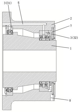
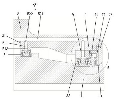
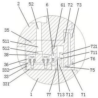
[0062] Such as Figure 1 to Figure 18 As shown, the bearing assembly for a wind power generator in this embodiment includes a rotating shaft 1 , a bearing seat 2 , a front bearing component 31 and a rear bearing component 32 . Among them, the rotating shaft 1 is connected with the rotor of the generator, and is used to transmit the torque and load of the rotor of the wind turbine, and is a rotating part; the bearing seat 2 is connected with the base of the generator, and bears the weight and other loads of the rotor of the wind turbine, and is a stationary component. Components; the front bearing part 31 and the rear bearing part 32 are arranged between the rotating shaft 1 and the bearing seat 2 to support the normal operation of the rotating shaft 1 and the parts between the rotating shaft 1 during the rotation. In this embodiment, both the front bearing component 31 and the rear bearing component 32 are sliding bearings 3 , and the sliding bearing 3 includes a bearing body ...

Embodiment 2

[0100] Figure 20 to Figure 29 It shows another embodiment of a bearing assembly for a wind power generator of the present invention, this embodiment is basically the same as the previous embodiment, the difference is that the sliding bearing 3 of this embodiment cancels the setting of the bearing housing 35, and A swing adjustment structure is provided between the radial shoe 33 and the bearing body 36 . That is, the swing form of setting the self-aligning block 39 between the radial shoe 33 and the bearing body 36 is used instead of the swing form of setting the swing adjustment part 38 between the bearing shell 35 and the bearing body 36, which solves the problem of load deflection. At the same time, the bearing arrangement space is minimized.

[0101] Specifically, the sliding bearing 3 further includes an aligning block 39 and a second limiting member. The self-aligning block 39 is installed on the radial tile 33, and the self-aligning block 39 is located between the ra...


PUM


Abstract

The invention provides a bearing assembly for a wind driven generator, which comprises a rotating shaft connected with a generator rotor, a bearing seat connected with a generator base, and a front bearing part and a rear bearing part which are arranged between the rotating shaft and the bearing seat and are sliding bearings, the sliding bearing comprises a bearing body and a plurality of radial tiles, and the radial tiles are fixedly installed on the inner side of the bearing body and arranged in the circumferential direction of the rotating shaft at intervals; the inner side surface of the radial tile is a radial bearing surface for bearing the radial load of the rotating shaft, and the radial bearing surface is provided with a first wear-resistant insulating layer. The device has the advantages of good shaft current insulation effect, convenience in operation and maintenance and the like.

Description

technical field [0001] The invention relates to the field of wind power generation, in particular to a bearing assembly for a wind power generator. Background technique [0002] In recent years, with the rapid development of offshore wind power generation technology, semi-direct drive generators have become one of the mainstream models of offshore wind power, and rolling bearing units are important supporting components of semi-direct drive generators. During the operation of the wind turbine, due to balance, air gap, load, friction, wiring and other reasons, it is easy to generate a potential difference near the rolling bearing unit, and it is easy to cause electric corrosion to the rolling bearing raceway and rolling body in the rolling bearing unit, which will cause damage to the rolling bearing, resulting in Problems such as abnormal noise and excessive vibration affect the service life of rolling bearings; and the rolling bearings used in wind turbines are large-sized b...

Claims


Application Information

Patent Timeline
Patent Type & Authority Applications(China)
IPC IPC(8): F16C17/26F16C23/04F16C25/04F16C33/20F16N1/00F03D80/70
CPCY02E10/72
Inventor 张亚宾杨志潘鸿鲁学良白尊洋朱杰周少华罗碧
Owner HUNAN CHONGDE IND TECH
Learn More