
LF (ladle furnace) dedusting and trapping system

A dust removal hood and furnace cover technology, which is applied to furnaces, furnace components, waste heat treatment, etc., can solve problems such as easy generation of eddy currents, smoke from the feeding slide pipe next to the furnace, and increased suction, so as to improve dust removal capabilities, eliminate air pollution, The effect of reduced upward resistance

Pending Publication Date: 2022-04-12
BAOSHAN IRON & STEEL CO LTD
View PDF9 Cites 0 Cited by
  • Summary
  • Abstract
  • Description
  • Claims
  • Application Information

AI Technical Summary

Problems solved by technology

[0009] 1. The main problem of the small fume hood of the LF furnace cover: the diameter of the hood is large, the electrode is blocked, and the eddy current is easily generated in the hood, which cannot effectively capture the flue gas, which is manifested as smoke from the 1# and 2# electrode holes;
[0010] Due to the large gap between the small smoke hood and the large smoke hood of the LF furnace cover, the air leakage is serious; the resistance of the lower water cooling plate is large, only a small amount of smoke is sucked from the side suction port, and a large amount of smoke and dust overflows from the furnace cover.
[0011] 2. The circular suction port of the LF furnace cover, the double action of arc and bottom blowing argon strong stirring, the steel slag splashes and sticks to the furnace cover, blocks the lower suction port, the dust removal ability of the furnace cover circular suction port cannot be fully exerted, and the smoke and dust bypass Furnace cover rising
[0012] 3. The observation door of the furnace cover has a long stroke, a large joint surface, and frequent movements, and the high-temperature flue gas overflow in the furnace cover has existed for a long time
[0013] 4. Smoke from the feeding chute next to the furnace Due to the large gap between the feeding ball valve and the valve seat at the side of the furnace, the smoke goes straight to the silo along the chute, and is discharged disorderly in the plant
[0014] 5. In order to reduce the spread of dust and increase suction, the dust removal fan is always switched at high speed, and cannot be operated at low speed with frequency conversion, resulting in high energy consumption
[0015] In summary, there are bottlenecks in the LF dust removal system: air leakage and smoke coexist at the furnace cover suction port, unreliable sealing of the alloy feeding ball valve beside the furnace, and dust overflow

Method used


Image

  • LF (ladle furnace) dedusting and trapping system
  • LF (ladle furnace) dedusting and trapping system
  • LF (ladle furnace) dedusting and trapping system

Examples


Embodiment Construction

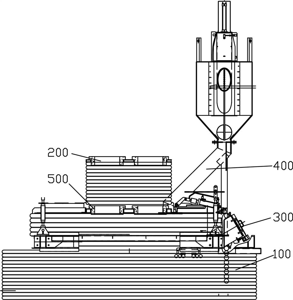
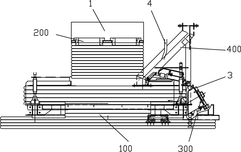
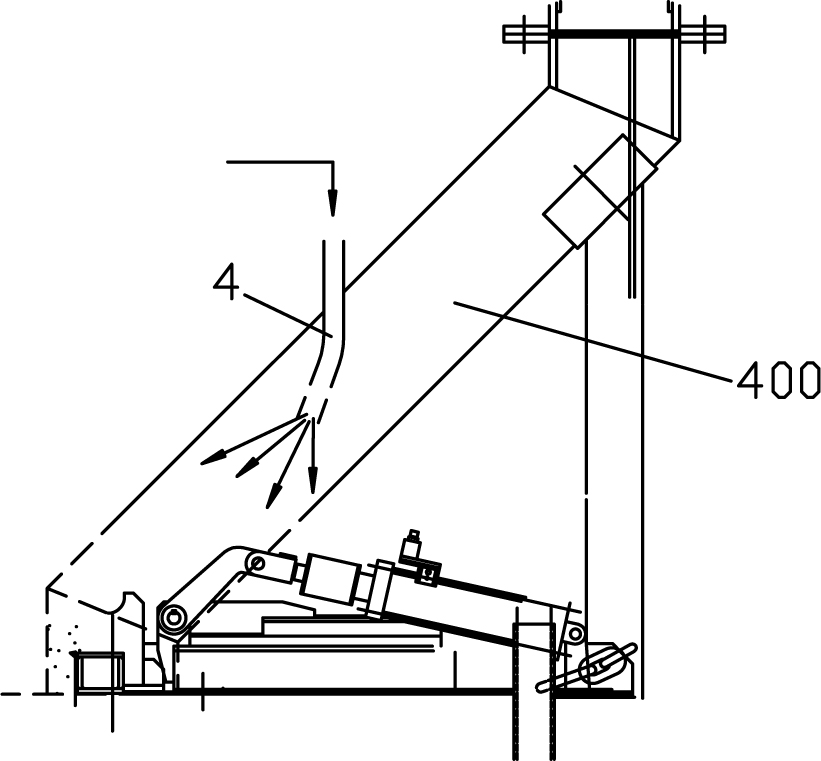
[0038] see Figure 1 to Figure 10 , the LF furnace dust collection system of the present invention is arranged on the LF furnace cover 100, which includes:

[0039] The dust removal cover 1 is a cylindrical structure; it is arranged at the electrode hole 200 of the furnace cover 100, and the top surface of the dust removal cover 1 is provided with three through holes 101 corresponding to the electrode holes. The sealing ring 2 is a pipe body, and its inner wall is evenly provided with a number of ventilation holes 21 along the circumferential direction. An air inlet port 22 is arranged on the air sealing ring 21, and is connected to the purge main pipe (not shown in the figure) through a pipeline; Dust removal holes and corresponding dust removal pipes are arranged symmetrically on both side walls of the dust removal cover 1, and the two dust removal pipes converge to the dust removal main pipe (not shown in the figure), and the dust removal pipe is connected to the main purge...


PUM


Abstract

The invention relates to an LF (ladle furnace) dedusting and trapping system, which comprises a dedusting cover, three through holes corresponding to the electrode holes are formed in the top surface of the dust removal cover, air seal rings are arranged at the through holes, the air seal rings are pipe bodies, vent holes are uniformly formed in the inner side walls of the air seal rings in the circumferential direction, and air inlet interfaces are formed in the air seal rings and are connected to a purging header pipe through pipelines; dust removal holes and corresponding dust removal pipes are symmetrically arranged on the side walls of the two sides of the dust removal cover, and the dust removal pipes are connected to the purging header pipe through pipelines; the observation door air sealing pipe is arranged at the observation door of the furnace cover and is rectangular, air outlet holes are uniformly formed in the inner side wall of the observation door air sealing pipe along the circumferential direction, and the axes of the air outlet holes are downward and form an angle with the horizontal plane; the observation door air sealing pipe is provided with an air inlet joint and is connected with a purging header pipe through a pipeline; and the lower part of the charging articulated chute purging pipe is inserted into the middle part of the charging articulated chute on one side of the furnace cover, the lower part of the charging articulated chute purging pipe positioned in the charging articulated chute is bent and forms an angle with the axis of the charging articulated chute, and the upper end of the charging articulated chute purging pipe is connected with the purging header pipe through a pipeline.

Description

technical field [0001] The invention relates to refining equipment outside a furnace, in particular to a dust removal and collection system for an LF furnace. Background technique [0002] The LF furnace strengthens the thermodynamic and kinetic conditions by means of arc heating, reducing atmosphere in the furnace, white slag refining, gas stirring, etc., so that the molten steel can achieve comprehensive refining effects such as deoxidation, desulfurization, alloying, and heating in a short time. For this purpose, the LF furnace is equipped with an electrode cross arm, a furnace cover, a wire feeder, an alloy feeding system and an emergency top gun. [0003] Among them, the furnace cover is the core equipment, a water-cooled hollow equipment, and the hub for all equipment in the LF furnace. see figure 1 , Furnace cover 100, electrode hole 200, observation door 300, feeding chute 400, lower water cooling plate 500. [0004] When energized, the cross-arm of the electrode ...

Claims


Application Information

Patent Timeline
Patent Type & Authority Applications(China)
IPC IPC(8): F27D17/00
Inventor 李胜平郑奋怡孙国湘蔡华
Owner BAOSHAN IRON & STEEL CO LTD
Learn More