
Mark point coordinate measuring method and system and deformation measuring method and system

A technology of coordinate measurement and marking points, which is applied in the field of vehicle crash test, can solve the problems of loss of precision, complicated operation, measurement of vehicle deformation area, etc., and achieve the effect of reducing consumption, high calculation accuracy and improving measurement efficiency

Pending Publication Date: 2022-04-12
DONGFENG MOTOR GRP
View PDF4 Cites 2 Cited by
  • Summary
  • Abstract
  • Description
  • Claims
  • Application Information

AI Technical Summary

Problems solved by technology

In the actual application process, the widely used articulated arm three-coordinate measuring machine has high measurement accuracy, but it may not be able to complete the measurement of the deformation area of ​​the vehicle at one time. Leapfrog jumping is required, the operation is more complicated, and it may cause certain accuracy loss
The 3D laser scanner is more convenient and quick to use, and can obtain the triangular mesh surface or point cloud data of the deformation area of ​​the body-in-white. However, in the actual application process of the 3D laser scanner, the measurement output is the triangular mesh surface or point cloud data, namely The acquired data is the surface position information of a continuous area, and the coordinate information of specific marking points on the surface of the body-in-white cannot be accurately picked up

Method used


Image

  • Mark point coordinate measuring method and system and deformation measuring method and system
  • Mark point coordinate measuring method and system and deformation measuring method and system
  • Mark point coordinate measuring method and system and deformation measuring method and system

Examples


Embodiment Construction

[0049] The specific embodiments of the present invention will be further described below in conjunction with the accompanying drawings. It should be noted here that the descriptions of these embodiments are used to help understand the present invention, but are not intended to limit the present invention.

[0050] Body-in-white: Refers to the welding assembly of body structural parts and covering parts, including front fenders, doors, engine hoods, and trunk lids, but excluding unpainted body parts of accessories and decorative parts.

[0051] Marking point: the identification point with numbered information drawn on the surface of the body-in-white with a marker pen or paint pen.

[0052] Target point: a special reflective point suitable for photogrammetry and scanning positioning that is matched with the 3D laser scanning measurement system. It is usually a sticky round sticker on the back, with a white circle in the middle and a black ring around it.

[0053] Target point...


PUM


Abstract

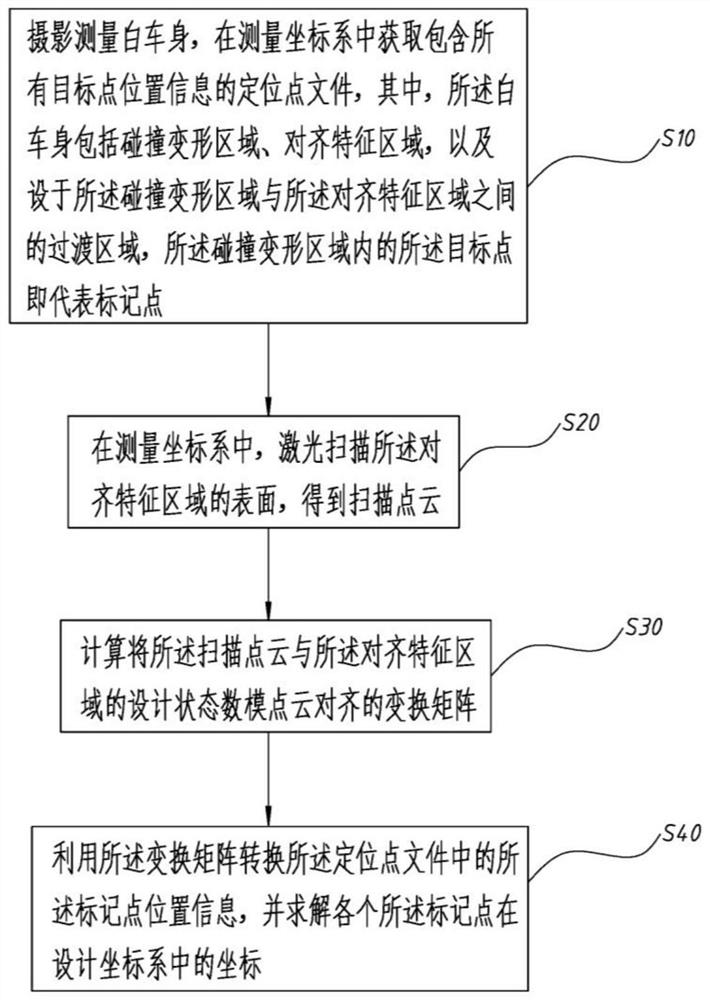
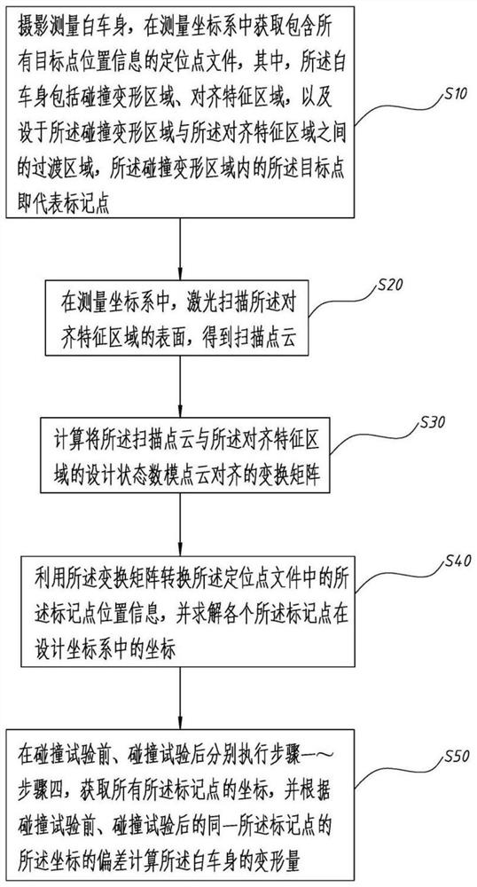
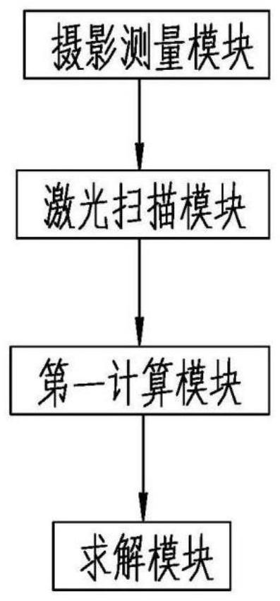
The invention discloses a mark point coordinate measuring method and system and a deformation measuring method and system. The mark point coordinate measurement method comprises the following steps: photogrammetric measurement of a body in white is carried out, and a positioning point file containing position information of all target points is obtained in a measurement coordinate system; in the measurement coordinate system, the surface of the feature area is aligned through laser scanning, and scanning point cloud is obtained; calculating a transformation matrix for aligning the scanning point cloud with the design state digital-analog point cloud of the alignment feature region; and converting the position information of the mark points in the positioning point file by using the transformation matrix, and solving the coordinates of each mark point in the design coordinate system. In the measurement coordinate system, position information of each target point is obtained through photogrammetry, point cloud data of the aligned feature area is obtained through laser scanning, then the point cloud data is aligned to a design state digital model, a transformation matrix for transformation from the body-in-white measurement coordinate system to the design coordinate system is obtained, and the position of each target point is transformed to obtain a design state digital model; and the coordinate value of the body-in-white mark point can be accurately obtained.

Description

technical field [0001] The invention relates to the technical field of vehicle crash tests, in particular to a method and system for measuring coordinates of a marked point, and a method and system for measuring deformation. Background technique [0002] In the process of passive safety development in automobile R&D and design, it is necessary to carry out the crash test and simulation analysis of the prototype vehicle. In the process of measuring the deformation of the crash test vehicle and benchmarking against the simulation results, it is necessary to use a three-dimensional coordinate measuring machine or a three-dimensional scanner to measure the deformation area of ​​the body-in-white in three dimensions. In the actual application process, the widely used articulated arm three-coordinate measuring machine has high measurement accuracy, but it may not be able to complete the measurement of the deformation area of ​​the whole vehicle at one time. Leapfrog jumping is req...

Claims


Application Information

Patent Timeline
IPC IPC(8): G01B11/00G01B11/16G01M17/007G01M7/08
Inventor 罗火贤季锋方璐祎徐自强刘世兵
Owner DONGFENG MOTOR GRP
Learn More