Heat energy storage test system and operation and control method thereof

A thermal energy storage and test system technology, applied in the direction of material thermal development, can solve the problems of manpower consumption, material and financial resources, poor flexibility, and high personnel costs, so as to reduce operation and maintenance costs, improve safety and accuracy, and improve human resources. effective effect

Pending Publication Date: 2022-04-12
思安新能源股份有限公司
View PDF0 Cites 0 Cited by
  • Summary
  • Abstract
  • Description
  • Claims
  • Application Information

AI Technical Summary

Problems solved by technology

[0003] At present, there is still a blank area in China for the high-automation and intelligent research of high-performance large-scale heat storage materials or test systems for heat storage devices. Colleagues who use industrial on-site control will have high risks, poor flexibility, original facility renovation costs, and personnel costs. The method and data of the load test characteristics can not be accurately collected according to the continuity of the test
Repeated testing is required, consuming a lot of manpower, material and financial resources

Method used


Image

  • Heat energy storage test system and operation and control method thereof
  • Heat energy storage test system and operation and control method thereof
  • Heat energy storage test system and operation and control method thereof

Examples


Embodiment 1

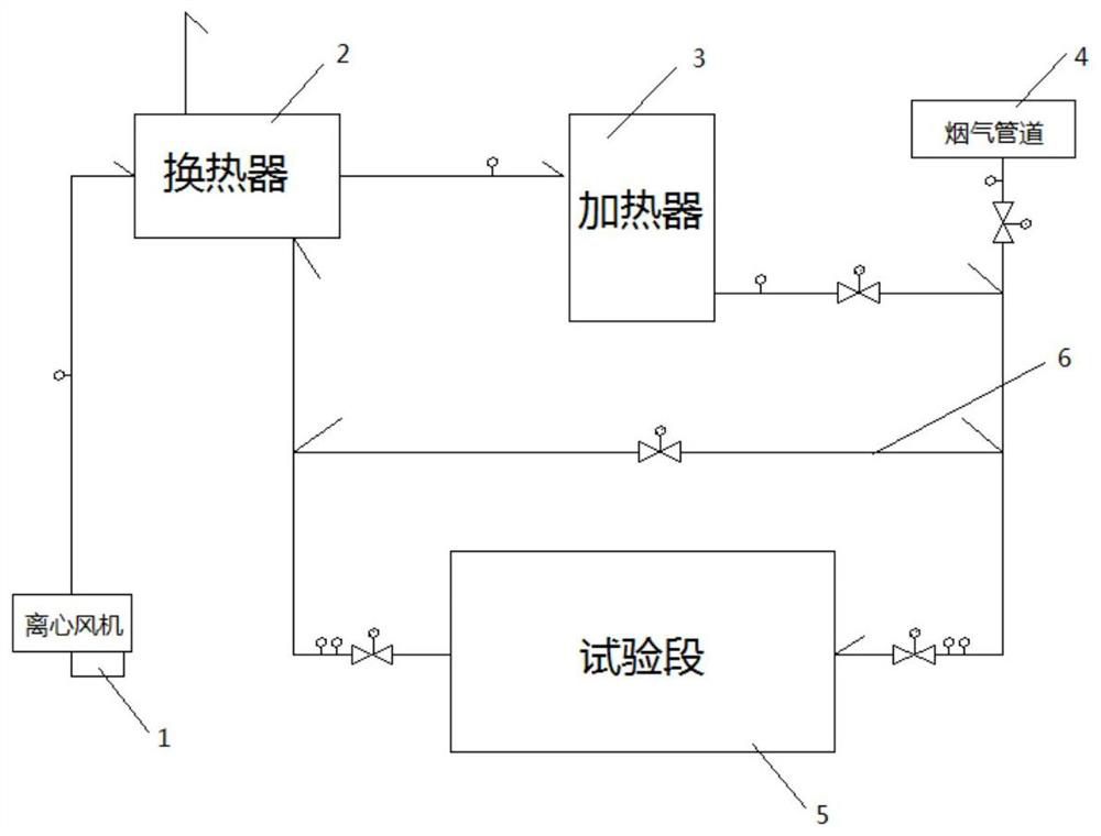
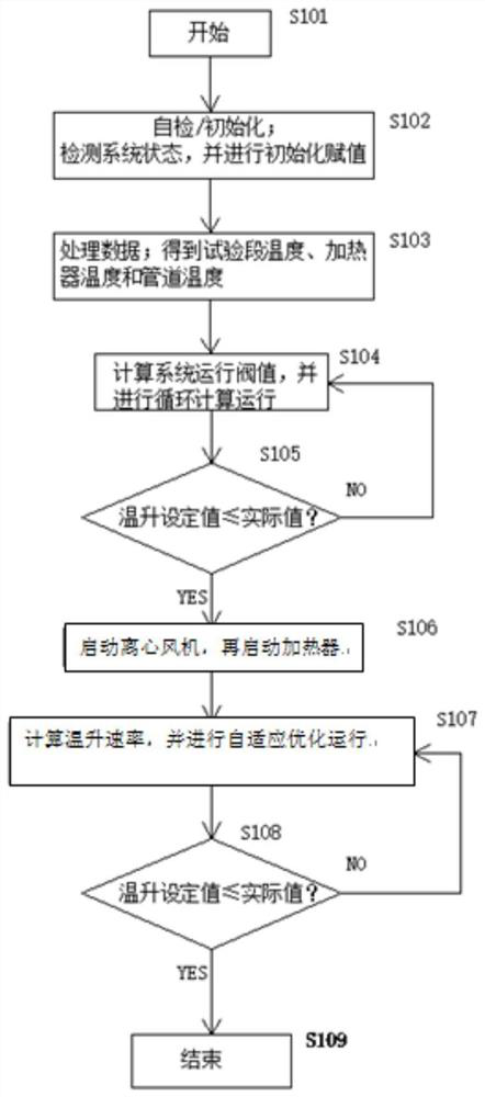
[0060] S101. Check the working status of each device, the working mode of the system and the initial logic of each switch are correct, and initialize and assign values ​​to each status and each control parameter.

[0061] S102, assuming that the target temperature value of the test section 5 is TS S = 320°C;

[0062] S103. Collect the inlet temperature TS1 of the test section 5 = 100°C, the outlet temperature TS0 of the heater 3 = 125°C, and the temperature TS2 of each connecting pipe = 120°C;

[0063] S104, calculate the test start threshold T of the whole system 0 k, and perform cyclic calculation operation; T 0 k=TS1+H / 8=140°C, H is calibration time=320°C;

[0064] S105,T 0 k>TS0, execute S106;

[0065] S106, start the centrifugal fan 1, and then automatically start the heater 3; the start-up interval between the centrifugal fan 1 and the heater 3 can be 5s;

[0066] S107. Calculate the temperature rise rate ΔTem=5°C in the test section 5, then Q 风(i+1) =800;

[006...

Embodiment 2

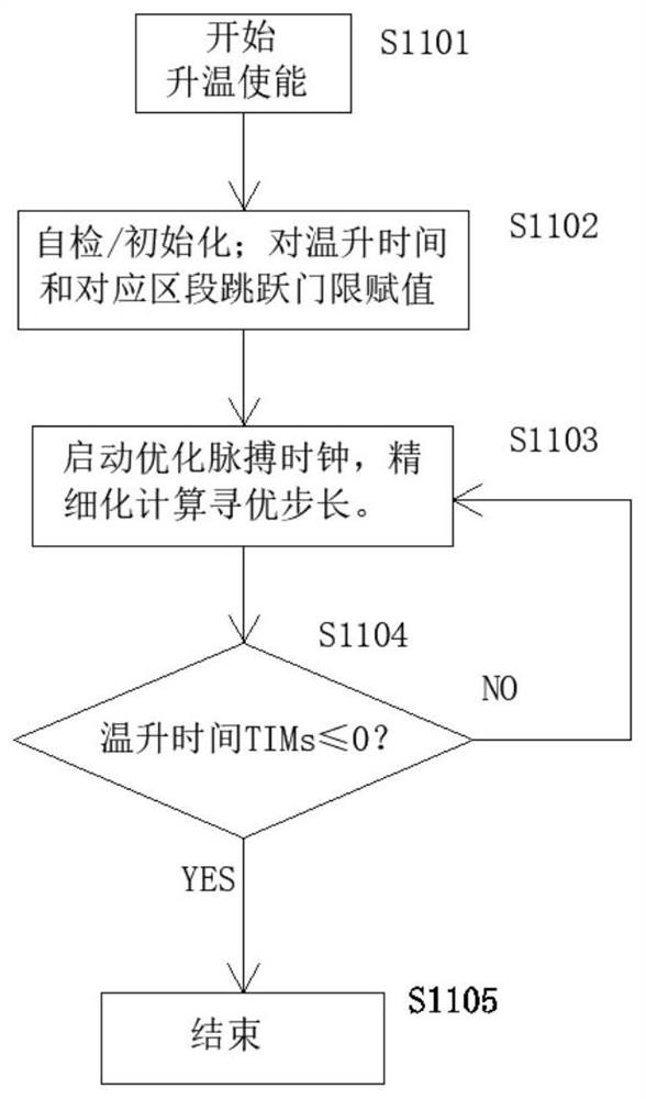
[0074] S1101, start, enable heating;

[0075] S1102. Set the temperature rise time of the test section 5 as section TIM 1 = 1h, TIM i =1h, the temperature rise section corresponding to each temperature rise time is TH 1 =130°C, TH i =135°C;

[0076] S1103. Start the self-learning optimization control pulse clock, and continuously calculate the dynamic temperature rise modulation step size ST according to the dynamic control refinement optimization self-applicable step size formula ki =0.08333°C / S, TIM i Enable ST ki action;

[0077] S1104. Continuously judge and update the control step size until the TIM of one test cycle ends and stops working.

[0078] The fourth technical solution provided by the present invention is a control method for refined cooling of the test section, based on a thermal energy storage test system, including the following:

[0079] S1201, start, enable cooling;

[0080] S1202, assuming that the cooling time of the test section 5 is respectivel...

Embodiment 3

[0084] S1201, start, enable cooling;

[0085] S1202, assuming that the cooling time of the test section 5 is respectively TIM 1 = 1h, TIM i =1h, the cooling section corresponding to each cooling time corresponds to TH 1 =135°C, TH i =130°C;

[0086] S1203, start the self-learning optimization control pulse clock, and continuously calculate the dynamic temperature modulation step size ST according to the dynamic control refinement optimization self-applicable step size formula k =-0.08333°C / S;

[0087] S1204 , continue to judge and update the control step size until the TIM of one test cycle ends and stops working.

[0088] The fifth technical solution provided by the present invention is an unattended automatic shift control method for the test section, based on a thermal energy storage test system, including the following:

[0089] S1301, start, enable the working system;

[0090] S1302, initialize the parameter setting, set the unattended running time TIM1 during the ...


PUM


Abstract

The invention discloses a heat energy storage test system and an operation and control method thereof, the heat energy storage test system comprises a test section used for placing a test piece to be tested, a heater connected in parallel with the test section, and a preheating pipeline connected between the test section and the heater; sensors are arranged at the two ends of the test section, the two ends of the heater and the preheating pipeline; the sensors comprise a temperature sensor, a pressure sensor and a flow sensor; wherein the heater is used for heating input normal-temperature gas and conveying the heated gas into the test section, and the test section is used for heating a test piece to be tested by using the heated gas. And the blank of an automatic and intelligent research test system for the heat storage material or the heat storage device in the prior art is filled.

Description

technical field [0001] The invention belongs to the technical field of energy storage, and in particular relates to a thermal energy storage test system and an operation and control method thereof. Background technique [0002] Thermal energy is one of the important energy sources in the national economy. In the production process, a large amount of intermittent or waste thermal energy is wasted due to lack of good storage and recycling. When thermal energy is used again, other energy sources (such as electric energy, etc.) ) to produce heat energy, which causes irrational use of energy and waste of energy. Research on a material or device that can effectively store heat energy has a huge beneficial effect on energy structure adjustment and energy saving and carbon reduction. Effectively storing and recovering heat energy and rationally adjusting the energy structure will produce huge social benefits, with an overall energy-saving and carbon-reducing space of about 30%-50%....

Claims


Application Information

Patent Timeline
IPC IPC(8): G01N25/20
CPCY02E60/14
Inventor 蔺海龙陈久林王成徐吉富许肖飞
Owner 思安新能源股份有限公司
Why Eureka
Try Eureka