
Automatic protection type multi-output power transformation device

A technology of automatic protection and transformer device, applied in measurement device, transformer/inductor cooling, transformer/inductor noise damping, etc., can solve problems such as affecting fetal development in the abdomen, damage to transformer longitudinal insulation, transformer body damage, etc. Achieve the effect of reducing damage, improving safety and efficiency, and improving accuracy

Pending Publication Date: 2022-04-12
史家兴
View PDF0 Cites 1 Cited by
  • Summary
  • Abstract
  • Description
  • Claims
  • Application Information

AI Technical Summary

Problems solved by technology

[0004] In addition, the low-frequency noise generated by most transformers and the noise generated by the heat dissipation system will cause chronic damage to the human body, easily make people irritable, irritable, and sometimes even lose their minds. If they are disturbed for a long time, they may also cause nervous system diseases such as neurasthenia and insomnia , if the pregnant woman is exposed to low-frequency noise for a long time, it will also affect the development of the fetus in the abdomen
At the same time, the oscillating shock wave generated by the outside world is more harmful to the longitudinal insulation of the transformer. The oscillating shock wave generated by the outside world acts on the shell to make it resonate with the transformer body, which will cause huge damage to the transformer body. The existing transformers have not improved this. measure

Method used


Image

  • Automatic protection type multi-output power transformation device
  • Automatic protection type multi-output power transformation device
  • Automatic protection type multi-output power transformation device

Examples


Embodiment Construction

[0029] The following will clearly and completely describe the technical solutions in the embodiments of the present invention with reference to the drawings in the embodiments of the present invention.

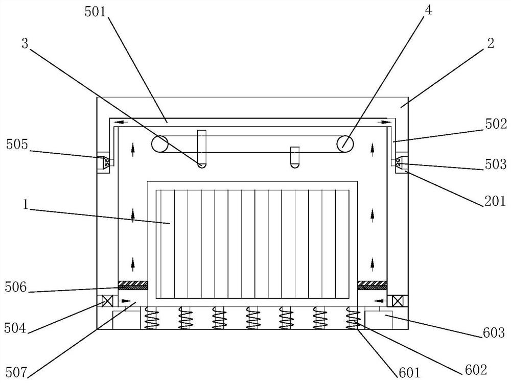
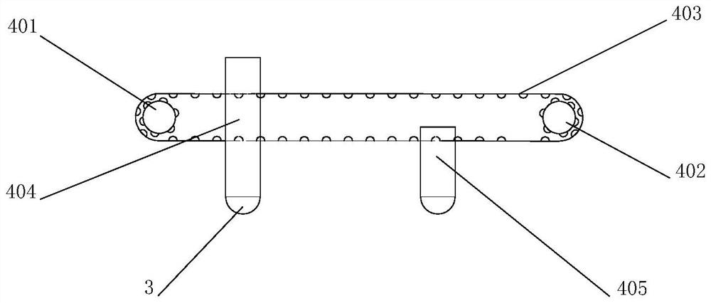
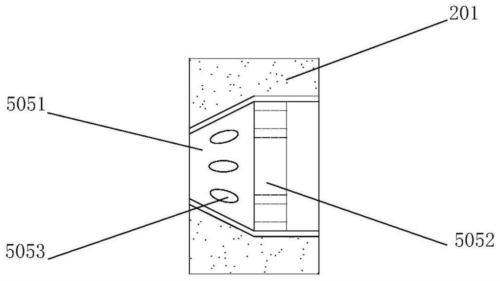
[0030] see Figure 1-5 , The present invention provides a technical solution: an automatic protection type multi-output power transformation device of the present invention, comprising a transformer body 1, a housing 2 for installing the transformer body 1, a monitoring system and a main control system. The monitoring system includes two infrared temperature measurement sensors 3, a mobile device 4 that drives the two infrared temperature measurement sensors 3 to move backwards or opposite directions, an imaging module, an image processing module, a smoke sensor, a gas concentration detector, four sets of switch valves, Vibration detector A and vibration sensor B. The infrared temperature measurement sensor 3 faces the transformer body 1 downward, and each infrared temperatur...


PUM


Abstract

The invention relates to an automatic protection type multi-output power transformation device. The automatic protection type multi-output power transformation device comprises a transformer body, a shell, a monitoring system and a main control system. The monitoring system comprises two infrared temperature measurement sensors, a moving device, an imaging module and an image processing module, the moving device drives the two infrared temperature measurement sensors to move back to back or in opposite directions, and the imaging module receives infrared ray difference, collected by the infrared temperature measurement sensors, in the transformer body and generates thermal imaging information of the transformer body. And the image processing module compares the thermal imaging information and positions abnormal infrared difference signals. The transformer body is provided with a plurality of input voltages, a plurality of output voltages and a plurality of independent transformation circuits. According to the automatic protection type multi-output power transformation device, an abnormal circuit in the transformer body can be identified and positioned through the infrared temperature measurement sensor, then the abnormal circuit is automatically closed through the main control system, the automatic protection function is achieved, and the safety of the transformer body is improved.

Description

technical field [0001] The invention relates to the field of electric equipment, in particular to an automatic protection type multi-output power transformation device. Background technique [0002] A transformer is a static electrical device used to convert AC voltage and current to transmit AC power. It is based on the principle of electromagnetic induction to achieve electrical energy transfer. Transformers can be divided into power transformers, test transformers, instrument transformers and special-purpose transformers according to their uses. Power transformer is a kind of transformer, which is a necessary equipment for power transmission and distribution and power user distribution, and can meet the needs of long-distance power transmission. [0003] However, in the long-distance power transmission process of the existing power transformer, due to the instability of the transformer transmission line, in many cases, only a very simple fault will lead to the collapse ...

Claims


Application Information

Patent Timeline
Patent Type & Authority Applications(China)
IPC IPC(8): H01F27/08H01F27/33H01F27/40F16F15/04G01D21/02
Inventor 史家兴
Owner 史家兴
Learn More