Vehicle-mounted transformer

A technology for transformers and outer surfaces, applied in the field of transformers, can solve the problems of leakage, lack, and incapacity of electrical equipment in bumpy vehicle conditions, and achieve the effect of changing the voltage regulation multiple.

Inactive Publication Date: 2022-04-12
时俊海
View PDF0 Cites 0 Cited by
  • Summary
  • Abstract
  • Description
  • Claims
  • Application Information

AI Technical Summary

Problems solved by technology

[0002] The on-board transformers of existing RVs are mostly divided into two working conditions when they are in use. One is that the on-board transformer is used to adjust the output voltage of the vehicle battery when it is working. , so that the battery can be used for power supply of 220V electrical appliances, and on the one hand, it may be used for charging and voltage regulation of solar panels, and the input terminal of these two usage methods, that is, the input voltage of the primary coil side is generally not constant, such as The voltage provided by the battery will gradually decrease as the internal power of the battery decreases. At this time, if the voltage regulation multiple of the transformer cannot be adjusted, the voltage at the output terminal will also decrease accordingly. At this time, power consumption may occur. When the equipment is weak, the voltage of the power generated by the solar panel absorbed by the solar energy is generally not constant. The traditional transformer can only ensure that the output voltage is within the threshold range, and cannot guarantee a constant output voltage. Currently, there is a lack of A vehicle-mounted transformer that can carry out stepless adjustment of voltage regulation multiples to adapt to voltage fluctuations at the input end and ensure a relatively constant voltage output at the output end. At the same time, current transformers are divided into two types: natural cooling and oil cooling. In the interior space of the vehicle, natural cooling cannot obtain a good cooling effect, and oil cooling is not suitable for bumpy vehicle conditions and is prone to leakage. Currently, there is a lack of a cooling structure that is easy to use and adapts to the vehicle.

Method used


Image

  • Vehicle-mounted transformer
  • Vehicle-mounted transformer
  • Vehicle-mounted transformer

Examples


Embodiment Construction

[0029] The following will clearly and completely describe the technical solutions in the embodiments of the present invention with reference to the accompanying drawings in the embodiments of the present invention. Obviously, the described embodiments are only some, not all, embodiments of the present invention. Based on the embodiments of the present invention, all other embodiments obtained by persons of ordinary skill in the art without making creative efforts belong to the protection scope of the present invention.

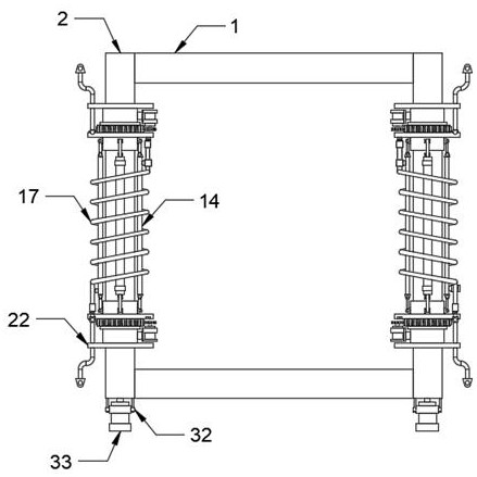
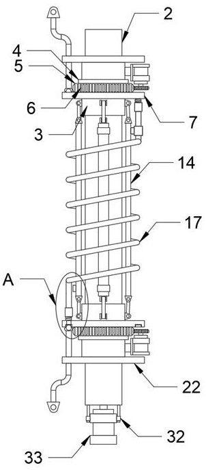
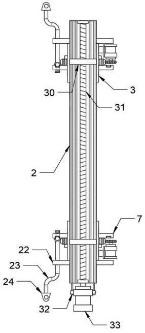
[0030] see Figure 1-10 , the present invention provides a technical solution: a vehicle-mounted transformer, the transformer includes a first iron core 1, a second iron core 2 is fixedly arranged on both sides of the first iron core 1, and the outer surface of the second iron core 2 is Both the upper end and the lower end are movably sleeved with a slider 3, and the outer surface of the slider 3 is provided with an adjustment mechanism, and the adjustment mec...


PUM


Abstract

The transformer comprises a first iron core, second iron cores are fixedly arranged on the two sides of the first iron core, the upper ends and the lower ends of the surfaces of the outer sides of the second iron cores are movably sleeved with sliding blocks, and adjusting mechanisms are arranged on the surfaces of the outer sides of the sliding blocks. The adjusting mechanism comprises an annular groove, a rotating ring, clamping teeth, a connecting ring, a first mounting seat, a first motor, a gear, a first transmission block, a first rotating shaft, a transmission rod, a tensioning block, a second transmission block and a second rotating shaft, the annular groove is fixedly formed in the surface film of the outer side of the sliding block, and the rotating ring is movably arranged in the annular groove in a clamped mode. And a plurality of clamping teeth are uniformly and fixedly arranged on the outer side surface of the rotating ring. According to the invention, the use effect is good, the number of turns of the cable wound on the outer side surface of the second iron core can be conveniently changed, so that the stepless voltage regulation multiple can be conveniently regulated, and stable voltage output can be provided when the input voltage fluctuates.

Description

technical field [0001] The invention relates to the field of transformers, in particular to a vehicle-mounted transformer. Background technique [0002] The on-board transformer of the existing RV is mostly divided into two working conditions when in use. One is that the on-board transformer is used to adjust the output voltage of the vehicle battery when it is working. , so that the battery can be used for power supply of 220V electrical appliances, and on the one hand, it may be used for charging and voltage regulation of solar panels, and the input terminal of these two usage methods, that is, the input voltage of the primary coil side is generally not constant, such as The voltage provided by the battery will gradually decrease as the internal power of the battery decreases. At this time, if the voltage regulation multiple of the transformer cannot be adjusted, the voltage at the output terminal will also decrease accordingly. At this time, power consumption may occur. ...

Claims


Application Information

Patent Timeline
Patent Type & Authority Applications(China)
IPC IPC(8): H01F29/02H01F27/36H01F27/29H01F27/08B01D46/10
Inventor 时俊海
Owner 时俊海
Why Eureka
Try Eureka