Antenna and preparation method thereof, millimeter wave sensor and terminal

An antenna and one-sided technology, applied in the field of antenna and its preparation, millimeter wave sensors and terminals, can solve the problem that the bandwidth cannot meet the needs of millimeter wave radar well

Pending Publication Date: 2022-04-12
HUAWEI TECH CO LTD
View PDF17 Cites 3 Cited by
  • Summary
  • Abstract
  • Description
  • Claims
  • Application Information

AI Technical Summary

Problems solved by technology

[0004] The application provides an antenna and its preparation method, a millimeter wave sensor and a terminal, which realizes double resonance through slot coupling, expands the bandwidth of

Method used


Image

  • Antenna and preparation method thereof, millimeter wave sensor and terminal
  • Antenna and preparation method thereof, millimeter wave sensor and terminal
  • Antenna and preparation method thereof, millimeter wave sensor and terminal

Examples


Embodiment 1

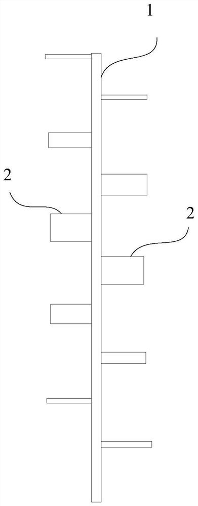
[0097] see Figure 2A As shown, the antenna provided in the embodiment of the present application can be a series antenna, which can be applied to sensors such as radar, and the antenna can include: a microstrip feeder 10, which can be arranged on a dielectric board 200a (see the following Figure 12A ) on one of the faces. Specifically, the dielectric board 200a may be a printed circuit board (PCB). And, the antenna also includes at least one group of the first group of radiating elements 21 located on the first side of the microstrip feeder 10 or the second group of radiating elements 22 located at the second side of the microstrip feeder 10, for example, see Figure 2A As shown, the antenna may include: located on the first side of the microstrip feeder 10 (for example Figure 2A The first group of radiating elements 21 on the right side of ) and the second side of the microstrip feeder 10 (for example Figure 2A The second group of radiation elements 22 on the left sid...

Embodiment 2

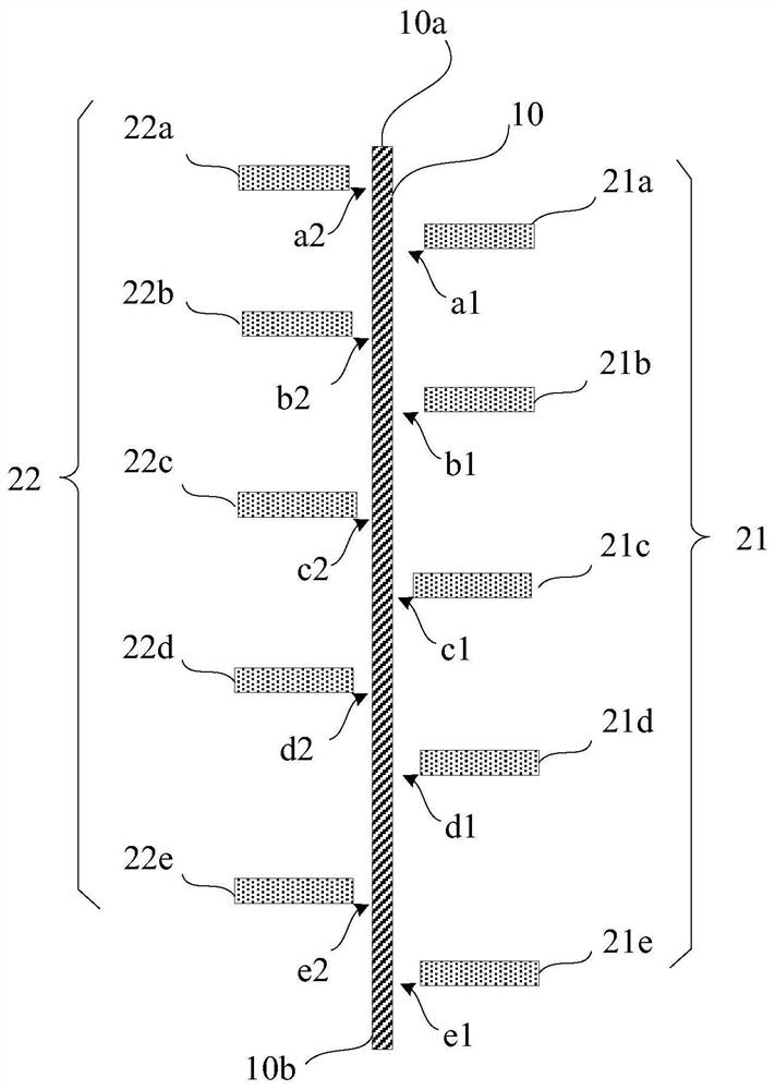
[0158] In the embodiment of the present application, low sidelobes are achieved by changing the width of the first coupling stub and / or the second coupling stub, for example, between at least one first coupling stub and / or at least one second coupling stub and the microstrip feeder 10 same gap, for example, as Figure 8A As shown, the gap between the five first coupling stubs (namely the first coupling stub 21a, the first coupling stub 21b, the first coupling stub 21c, the first coupling stub 21d and the first coupling stub 21e) and the microstrip feeder 10 a1, gap b1, gap c1, gap d1, and gap e1 may be the same. The gaps a2, gap b2, gap c2, gap d2, and gap e2 may be the same.

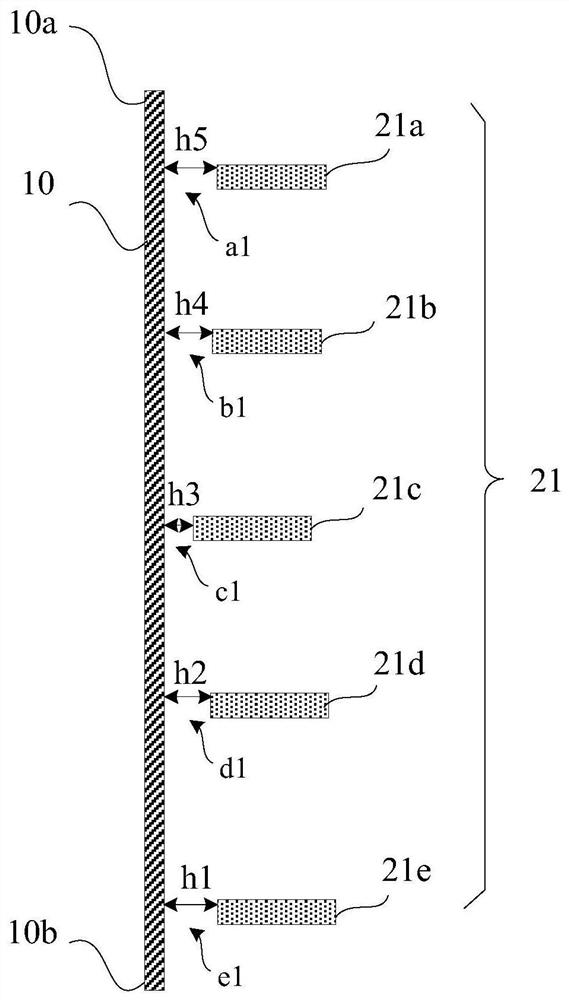
[0159] In order to achieve the low sidelobe effect, the number of the first coupling stub can be greater than or equal to 3, the number of the second coupling stub can be greater than or equal to 3, and the width of at least one first coupling stub meets the requirements from the first end 10a of the ...


PUM

PropertyMeasurementUnit
Widthaaaaaaaaaa
Lengthaaaaaaaaaa
Thicknessaaaaaaaaaa

Abstract

According to the antenna and the preparation method thereof, the millimeter wave sensor and the terminal provided by the embodiment of the invention, the gaps exist between the plurality of coupling branches and the microstrip feed line, so that a resonant structure (namely LC) is formed between the plurality of coupling branches and the microstrip feed line, and the antenna generates another resonance, so that the antenna can generate two resonance points; a larger bandwidth is realized, the range resolution of the millimeter-wave radar is improved, and the problem that the bandwidth of the existing antenna cannot meet the use of the millimeter-wave radar in long-distance and medium-distance scenes is solved. Furthermore, according to the method, the capability of an advanced driving assistance system (ADAS) of the terminal in automatic driving or auxiliary driving is improved, and the method can be applied to the Internet of Vehicles, such as vehicle external connection (V2X), inter-vehicle communication long term evolution (LTE-V), vehicle-vehicle (V2V) and the like.

Description

technical field [0001] The present application relates to the technical field of antennas, in particular to an antenna and a preparation method thereof, a millimeter wave sensor and a terminal. Background technique [0002] Radar is an electronic device that uses electromagnetic waves to detect targets. The radar emits electromagnetic waves to irradiate the target and receive its echo, thereby obtaining information such as the distance from the target to the electromagnetic wave emission point, the distance change rate (radial velocity), azimuth, height and other information. According to the radar frequency band, it can be divided into: over-the-horizon radar , microwave radar, millimeter wave radar and lidar. Among them, the millimeter wave radar is a radar that works in the millimeter wave band (millimeter wave). The millimeter wave band refers to the band in the 30-300GHz frequency domain (wavelength is 1-10mm). The wavelength of the millimeter wave is between the micro...

Claims


Application Information

Patent Timeline
IPC IPC(8): H01Q1/36H01Q1/50H01Q1/38
CPCH01Q1/3233H01Q21/0037H01Q9/0457H01Q5/307H01Q1/38H01Q1/50H01F2005/027H05K2201/10098G01S13/02H01Q21/061
Inventor 蔚停停李浩伟高翔刘一廷闫晨
Owner HUAWEI TECH CO LTD
Why Eureka
Try Eureka