
Driving pump, cold plate assembly, mobile terminal device and electronic system

A technology for driving pumps and components, which is applied to pump components, mechanical equipment, components of pumping devices for elastic fluids, etc., and can solve problems such as poor heat dissipation performance of the heat dissipation system and inability to meet the heat dissipation needs of products

Active Publication Date: 2022-04-12
HUAWEI TECH CO LTD
View PDF4 Cites 1 Cited by
  • Summary
  • Abstract
  • Description
  • Claims
  • Application Information

AI Technical Summary

Problems solved by technology

[0003] However, some components in the heat dissipation system formed by the existing mobile terminal equipment, due to product defects, lead to poor heat dissipation performance of the entire heat dissipation system, which cannot meet the heat dissipation needs of the product

Method used


Image

  • Driving pump, cold plate assembly, mobile terminal device and electronic system
  • Driving pump, cold plate assembly, mobile terminal device and electronic system
  • Driving pump, cold plate assembly, mobile terminal device and electronic system

Examples


Embodiment 1

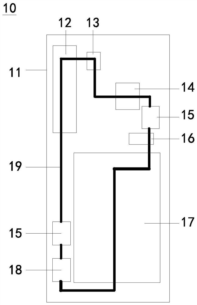
[0128] figure 1 It shows a structural frame diagram of the mobile terminal device 10 of the first embodiment. Such as figure 1 As shown, the mobile terminal device 10 may include a housing 11, and the housing 11 may be a single housing or a housing assembly assembled from several housings.

[0129] Such as figure 1 As shown, the mobile terminal device 10 may also include a heat generating device located in the casing 11 , a driving pump 18 , a liquid cooling control device 15 and a liquid cooling pipeline 19 . The liquid cooling pipeline 19 is connected to the driving pump 18 and the liquid cooling control device 15, and can pass through the heating element. There is flowable working medium in the liquid cooling pipeline 19 , the driving pump 18 and the liquid cooling control device 15 , and the liquid cooling pipeline 19 , the driving pump 18 and the liquid cooling control device 15 can constitute a flow pipeline of the working fluid.

[0130] The working medium can be co...

Embodiment approach 1

[0188] The scheme of Embodiment 1 can absorb impurities in the filter screen 152 by designing the liquid cooling control device 15, thereby blocking impurities in the liquid cooling control device 15, preventing them from entering the driving pump 18, and ensuring the working performance of the driving pump 18 , to avoid abnormalities such as stalling and noise in the drive pump 18.

[0189] Such as Figure 14 As shown, different from the liquid cooling control device 15 in the first embodiment, the liquid cooling control device 15 in the second embodiment may include at least two filters, such as the first filter 153, the second filter 154 and the third filter Net 155. The first filter 153 , the second filter 154 and the third filter 155 are arranged in sequence, the first filter 153 is close to the inlet 151 a, and the third filter 155 is close to the outlet 151 b. Each filter net can be connected, or can not be connected and keep a distance, for example, the first filter ...

Embodiment approach 2

[0191] The working principle of the liquid cooling control device 15 in the second embodiment is: when the working fluid carries impurities from the inlet 151a into the inner cavity of the housing 151, the impurities with larger particle sizes will be absorbed by the first filter screen 153, and the particles with larger particle sizes will be absorbed by the first filter screen 153. Medium ones will be adsorbed by the second filter screen 154 , and those with smaller particle diameters will be adsorbed by the third filter screen 155 . That is to say, the liquid cooling control device 15 has a hierarchical filtering function.

[0192] The scheme of Embodiment 2 can make the total fluid impedance of the liquid cooling control device 15 smaller by designing multi-stage filter nets, with better filtering effect, high reliability and longer replacement period.

[0193] Such as Figure 15 As shown, different from the above embodiments, the housing 151 of the liquid cooling control...


PUM


Abstract

The invention provides a driving pump, a cold plate assembly, mobile terminal equipment and an electronic system. Wherein an impeller of the driving pump and the bearing are connected into a whole, the rotating shaft and the base are connected into a whole, and the bearing is in running fit with the rotating shaft and can rotate around the rotating shaft. The cold plate assembly comprises a cold plate and a water nozzle connected with the cold plate, and the thickness of the cold plate does not exceed 1.5 mm. The mobile terminal equipment comprises the driving pump or the cold plate assembly. The electronic system comprises a mobile terminal device and peripherals, the mobile terminal device can independently carry out liquid cooling heat dissipation, and a three-way device is arranged in the mobile terminal device. The peripheral is detachably connected with the mobile terminal equipment, and when the peripheral is connected with the mobile terminal equipment, the three-way device can communicate the internal liquid cooling pipeline of the mobile terminal equipment with the external liquid cooling pipeline of the peripheral, so that the peripheral and the mobile terminal equipment integrally form a liquid cooling heat dissipation system. According to the scheme, the product performance of the driving pump and the cold plate assembly can be improved, and therefore the heat dissipation performance of the liquid cooling heat dissipation system is guaranteed.

Description

technical field [0001] The present application relates to the technical field of terminal equipment, in particular to a driving pump, a cold plate assembly, a mobile terminal equipment and an electronic system. Background technique [0002] With more and more functions and stronger performance of mobile terminal equipment, the heat generated by it also increases sharply. If there is no effective heat dissipation design, the accumulation of heat or cold will cause the temperature of the mobile terminal device to be too high or too low, resulting in degraded and limited device performance, poor user thermal experience, reduced reliability of the device, battery safety, etc. influences. Therefore, the heat dissipation design of mobile terminals has not only become one of the important bottlenecks in improving the device performance and reliability of mobile terminals, but also one of the most concerned indicators for consumers. [0003] However, some components in the heat di...

Claims


Application Information

Patent Timeline
Patent Type & Authority Applications(China)
IPC IPC(8): H05K7/20F04D13/06F04D29/22F04D29/20F04D29/66
CPCH05K7/20F04D13/06F04D29/22F04D29/66F04D29/20
Inventor 靳林芳吴睿康陈奇王英先刘毅陈丘王风平刘用鹿李思杨
Owner HUAWEI TECH CO LTD
Learn More