Exhaust control system of hemoperfusion device

A blood perfusion device and control system technology, applied in the field of exhaust control system, can solve the problems of reducing the effectiveness and safety of the cytokine adsorption column, reducing the contact between blood and resin, increasing the risk of coagulation in treatment, and improving the exhaust effect. , Guaranteed safety and efficacy, Light weight effect

Pending Publication Date: 2022-04-15
JAFRON BIOMEDICAL
View PDF5 Cites 0 Cited by
  • Summary
  • Abstract
  • Description
  • Claims
  • Application Information

AI Technical Summary

Problems solved by technology

[0006] However, with the continuous research on the clinical treatment of hemoperfusion devices, technicians have gradually developed new types of hemoperfusion devices; the latest hemoperfusion device developed by Jianfan Biotechnology Group Co., Ltd.: cytokine adsorption column (Jianfan Biotechnology Co., Ltd. CA series products of Science and Technology Group Co., Ltd.) as an example, compared with the HA series hemoperfusion device in the traditional technology, the adsorbent inside the cytokine adsorption column adopts resin with small particles, light weight and strong hydrophobicity, and the cytokine adsorption The volume of the column is full; if the traditional exhaust method is still used, the exhaust degree cannot be monitored and it is easy to cause insufficient exhaust. The residual air bubbles will reduce the contact between blood and resin, increase the risk of blood coagulation during treatment, and reduce the loss of cells. The effectiveness and safety of factor adsorption columns in the process of hemoperfusion therapy affect the clinical application of such adsorption columns

Method used


Image

  • Exhaust control system of hemoperfusion device
  • Exhaust control system of hemoperfusion device
  • Exhaust control system of hemoperfusion device

Examples


Embodiment Construction

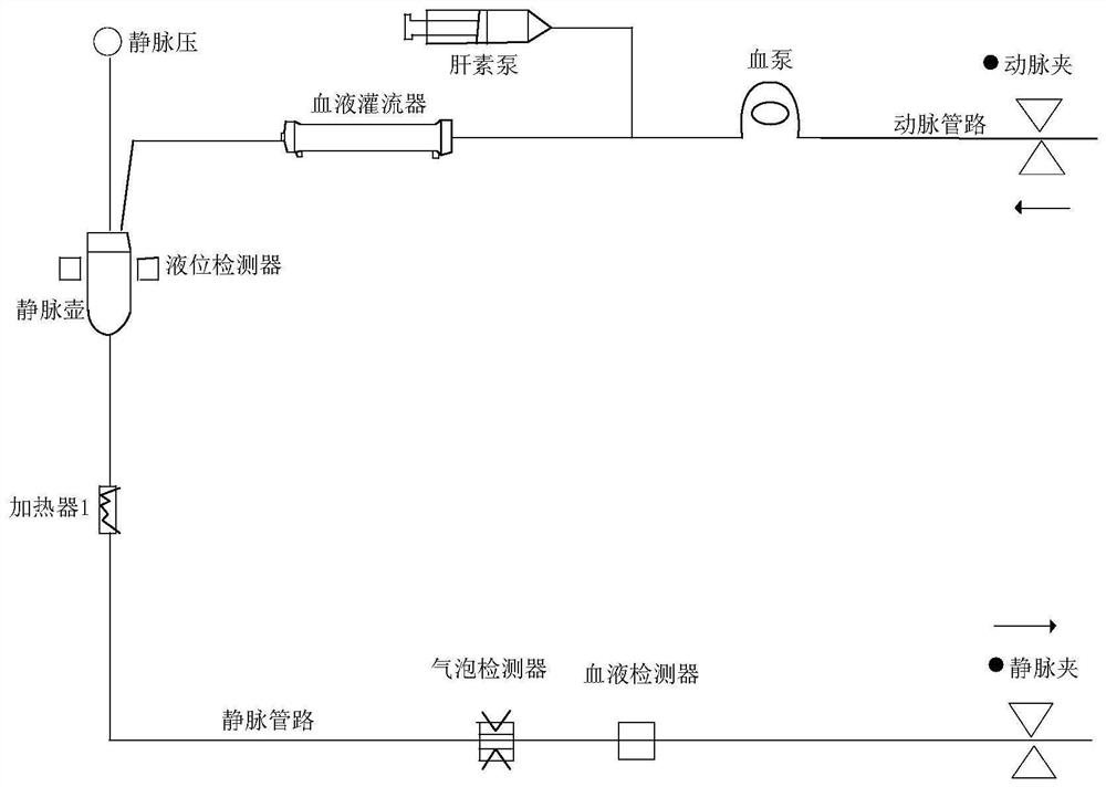
[0062] In order to better illustrate the embodiments of the present invention, the hemoperfusion device described in this embodiment adopts the mechanical structure of the hemoperfusion device in the CN201211354Y patent document or a similar structure, that is, the hemoperfusion device includes an adsorption column, and the adsorption column has The hollow filter chamber is filled with resin adsorbent, and the two ends of the adsorption column are provided with an inlet port and an outlet port, which are respectively used for connecting the arterial pipeline and the venous pipeline. The process and principle of purifying blood by the above-mentioned hemoperfusion device are: figure 1 As shown, the arterial pipeline is driven by the blood pump to introduce the blood of the human body to the inlet end of the hemoperfusion device, and the blood directly contacts the solid adsorbent in the adsorption column, and removes middle molecules or large molecules in the blood by adsorption...


PUM


Abstract

The invention discloses an exhaust control system of a hemoperfusion device, which is characterized in that the bubble amount of liquid on a vein pipeline is detected through a first detection module, and the pre-flushing exhaust time of an adsorption column is detected through a time detection module; and the state of the pre-flushing liquid flowing and exhausting stage is monitored by combining the bubble amount of the liquid on the vein pipeline and the pre-flushing and exhausting time of the adsorption column, and whether the exhausting stage needs to be stopped or not is judged. Besides, in the pre-flushing liquid flowing exhaust stage or after the pre-flushing liquid flowing exhaust stage, the angle of the adsorption column can be adjusted through the clamping module, or the adsorption column is knocked through the knocking module, or the adsorption column is rotated through the rotating module, or the air bubbles hidden in the corners of the adsorption column can be further exhausted through the combination of the clamping module, the knocking module and the rotating module; the method is very suitable for exhaust control of the cytokine adsorption column adopting resin which is small in particle, light in weight and high in hydrophobicity as an adsorbent, and the exhaust effect of the cytokine adsorption column is effectively improved.

Description

technical field [0001] The invention belongs to the technical field of medical equipment, and in particular relates to an exhaust control system of a hemoperfusion device. Background technique [0002] Hemoperfusion is a kind of equipment used in blood purification treatment. Its working principle is: draw the patient's blood out of the body, and make this part of the blood contact with the adsorbent in the hemoperfusion, and remove some external substances by adsorption. Source or endogenous toxins, and return the purified blood to the patient, so as to achieve the therapeutic purpose of purifying the blood. [0003] figure 1 It shows a circuit schematic diagram of an embodiment in which a hemoperfusion device is applied to clinical treatment, wherein the extracorporeal circulation circuit (including: arterial circuit and venous circuit) is used to transmit blood, and the hemoperfusion device is used to remove Certain exogenous or endogenous toxins. According to the diff...

Claims


Application Information

Patent Timeline
IPC IPC(8): A61M1/36
Inventor 董凡宁偲偲周峰谭明圆
Owner JAFRON BIOMEDICAL
Why Eureka
Try Eureka