Parallel side beam structure for electric vehicle

A technology for electric vehicles and side beams, which is applied in the directions of motor vehicles, substructures, superstructures, etc., can solve the problems of damage and large deformation of the sidebars, and achieve the effects of reducing weight, improving performance and reducing costs.

Pending Publication Date: 2022-04-15
HYUNDAI MOTOR CO LTD +1
View PDF0 Cites 0 Cited by
  • Summary
  • Abstract
  • Description
  • Claims
  • Application Information

AI Technical Summary

Problems solved by technology

Specifically, steel-pressed side beams not only have a directionality that is favorable for supporting longitudinal loads, thus being easily damaged by lateral impacts of side-bar collisions, but also have a large deformation of the cross-section of steel-pressed parts compared with aluminum extruded materials, It is thus inevitably disadvantageous in terms of impact energy support performance

Method used


Image

  • Parallel side beam structure for electric vehicle
  • Parallel side beam structure for electric vehicle
  • Parallel side beam structure for electric vehicle

Examples


Embodiment Construction

[0038] The following description is merely exemplary in nature and is not intended to limit the invention, application or uses. It should be understood that throughout the drawings, corresponding reference numerals indicate like or corresponding parts and features.

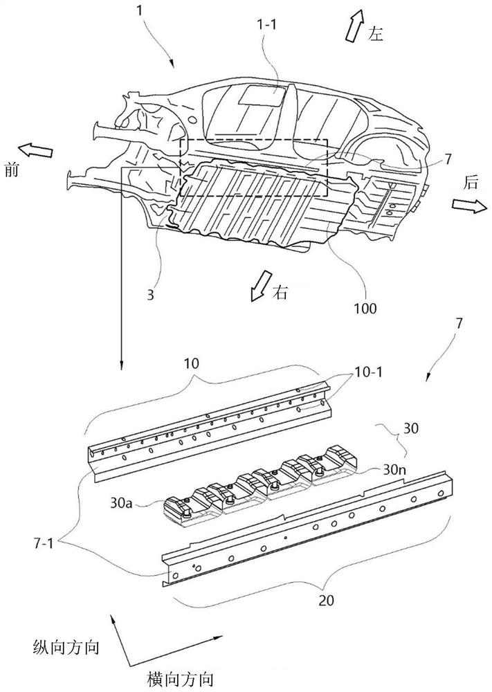
[0039] refer to figure 1 , the electric vehicle 1 includes side members 7 attached to lower portions of left and right side surfaces of the vehicle body frame 1-1.

[0040] Specifically, the vehicle body frame 1-1 includes a center floor 3 and a seat cross member 5 (refer to Figure 4 ). For example, the body shape body constitutes the body frame, the center floor 3 provides a place where the high voltage battery 100 is installed on its lower surface, and the seat cross member 5 supports lateral deformation of the side members 7 as a cross member in the center floor 3 .

[0041] Specifically, the central floor 3 forms a stepped portion (see Figure 4 to Figure 6 ), so that the side beams 7 are located on the l...


PUM


Abstract

A side-by-side type side beam structure for an electric vehicle includes: a side beam inner portion located on a side surface of a center floor, where the center floor forms an underbody, a side beam outer portion, and a plurality of side-by-side members; the side beam outer part is coupled to the side beam inner part and is configured to form a side beam inner space; a plurality of side-by-side members are provided in the side sill interior space in a longitudinal direction of the vehicle.

Description

technical field [0001] The present invention relates to a side sill structure for an electric vehicle, in particular, to a scrum type side sill structure for an electric vehicle. Background technique [0002] The statements in this section merely provide background information related to the present disclosure and may not constitute prior art. [0003] Typically, electric vehicles meet the requirement for extended driving range by increasing the size of the high-voltage cells in the battery. [0004] The reason is that electric vehicles can place the high-voltage battery at the lower end of the center floor, rather than the traditional method of placing the high-voltage battery on the rear floor, which is often used in internal combustion engine vehicles. Specifically, the lower end of the center floor has structural features capable of securing a layout that facilitates increasing the size of the high-voltage battery. [0005] Furthermore, in recent years, with the rapid ...

Claims


Application Information

Patent Timeline
Patent Type & Authority Applications(China)
IPC IPC(8): B62D25/02B62D25/20
CPCB62D25/025B62D27/065B62D21/157B60K1/04B60K2001/0438B60Y2306/01B60Y2200/91B60Y2410/124
Inventor 黄昌燮韩昇佑朴大明孙景薰
Owner HYUNDAI MOTOR CO LTD
Why Eureka
Try Eureka