Supercharge Your Innovation With Domain-Expert AI Agents!

MEMS wafer bonding mechanism and in-situ deblocking method of MEMS wafer bonding

A wafer bonding and bonding technology, which is applied in the field of micro-electromechanical systems and can solve problems such as removal of silicon caps

Pending Publication Date: 2022-04-15
CHINA ELECTRONICS PROD RELIABILITY & ENVIRONMENTAL TESTING RES INST THE FIFTH ELECTRONICS RES INST OF MIITCEPREI LAB
View PDF0 Cites 0 Cited by
  • Summary
  • Abstract
  • Description
  • Claims
  • Application Information

AI Technical Summary

Problems solved by technology

[0003] Based on this, it is necessary to address the problem that the traditional method cannot effectively remove the silicon cap from the MEMS wafer bonding mechanism, and provide a MEMS wafer bonding mechanism and an in-situ unsealing method for MEMS wafer bonding

Method used


Image

  • MEMS wafer bonding mechanism and in-situ deblocking method of MEMS wafer bonding
  • MEMS wafer bonding mechanism and in-situ deblocking method of MEMS wafer bonding
  • MEMS wafer bonding mechanism and in-situ deblocking method of MEMS wafer bonding

Examples


Embodiment Construction

[0021] In order to make the above objects, features and advantages of the present invention more comprehensible, specific implementations of the present invention will be described in detail below in conjunction with the accompanying drawings. In the following description, numerous specific details are set forth in order to provide a thorough understanding of the present invention. However, the present invention can be implemented in many other ways different from those described here, and those skilled in the art can make similar improvements without departing from the connotation of the present invention, so the present invention is not limited by the specific embodiments disclosed below.

[0022] In describing the present invention, it should be understood that the terms "center", "longitudinal", "transverse", "length", "width", "thickness", "upper", "lower", "front", " Back", "Left", "Right", "Vertical", "Horizontal", "Top", "Bottom", "Inner", "Outer", "Clockwise", "Counte...


PUM


Abstract

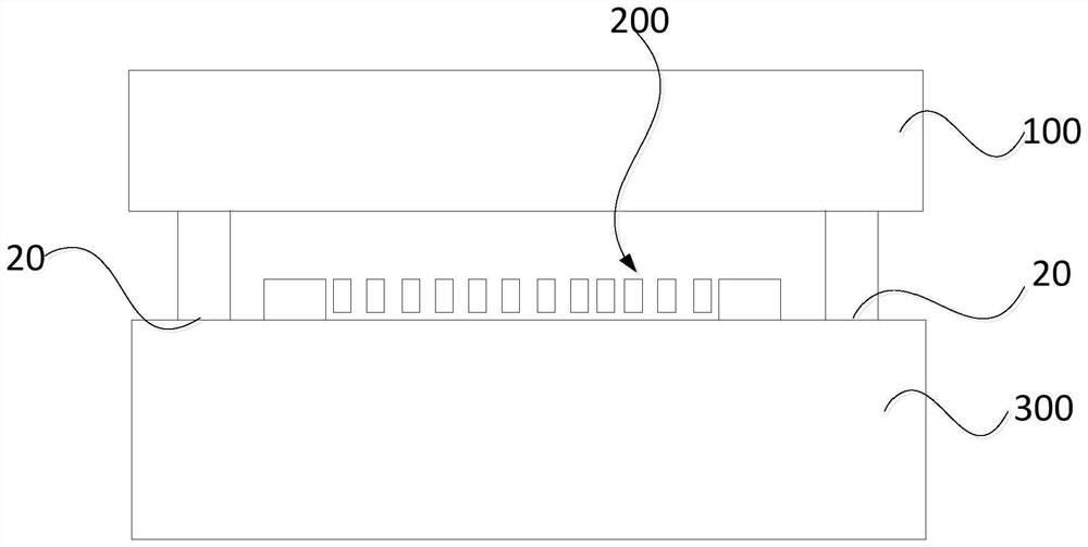
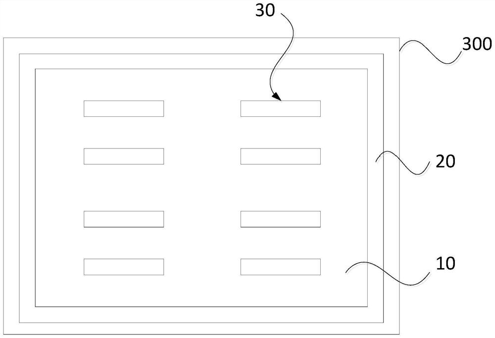
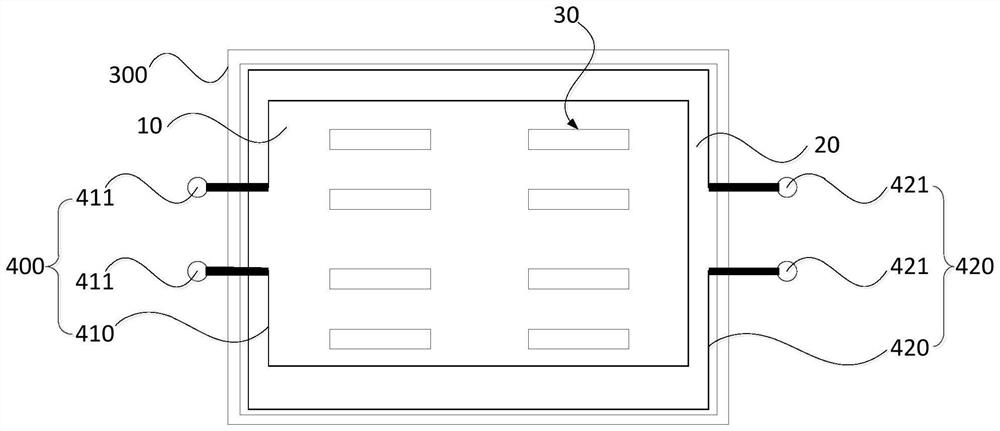
The invention relates to an MEMS (Micro Electro Mechanical System) wafer bonding mechanism and an in-situ deblocking method of MEMS wafer bonding. The MEMS wafer bonding mechanism comprises a cap piece, an MEMS functional part, a supporting piece and a first heating assembly, the cap piece is bonded on the supporting piece, the cap piece and the supporting piece are matched to form a bonding part, the MEMS functional part is bonded on the bonding part, the first heating assembly is arranged on the supporting piece, and the supporting piece is arranged on the supporting piece. And the first heating assembly is used for carrying out heating treatment on the bonding part of the cap piece and the supporting piece. Compared with a traditional in-situ unsealing mode, the MEMS wafer bonding mechanism can achieve in-situ unsealing of the cap piece and the supporting piece in a more targeted mode.

Description

technical field [0001] The invention relates to the technical field of micro-electromechanical systems, in particular to a MEMS wafer bonding mechanism and an in-situ unsealing method for MEMS wafer bonding. Background technique [0002] Micro-Electro-Mechanical-System (MEMS) is manufactured on the basis of microelectronics manufacturing technology combined with micromachining technology. Typical MEMS devices include accelerometers, gyroscopes, pressure sensors, microphones, and micromirrors. MEMS devices have many advantages such as small size, light weight, low power consumption, low cost, and easy integration. They have been widely used in many fields such as consumer electronics, automobiles, industry, biomedicine, aerospace, and national defense. Since the MEMS wafer bonding process puts a silicon cap on the upper surface of the MEMS wafer bonding mechanism, the MEMS functional components are hermetically packaged at the wafer level, making it impossible to directly obs...

Claims


Application Information

Patent Timeline
IPC IPC(8): B81C1/00B81B7/02
Inventor 董显山黄云黄钦文苏伟李仕远
Owner CHINA ELECTRONICS PROD RELIABILITY & ENVIRONMENTAL TESTING RES INST THE FIFTH ELECTRONICS RES INST OF MIITCEPREI LAB
Features
  • R&D
  • Intellectual Property
  • Life Sciences
  • Materials
  • Tech Scout
  • Unparalleled Data Quality
  • Higher Quality Content
  • 60% Fewer Hallucinations
Learn More