
Electrolytic bath

A technology of electrolytic cell and electrode sheet, which is applied in the direction of electrolytic process, electrolytic components, cells, etc. It can solve the problems of limited working efficiency of electrolytic cells and the inability to increase the speed of gas precipitation, etc., and achieve the effect of grounding stability

Pending Publication Date: 2022-04-15
南京氢灵新能源科技有限公司
View PDF1 Cites 0 Cited by
  • Summary
  • Abstract
  • Description
  • Claims
  • Application Information

AI Technical Summary

Problems solved by technology

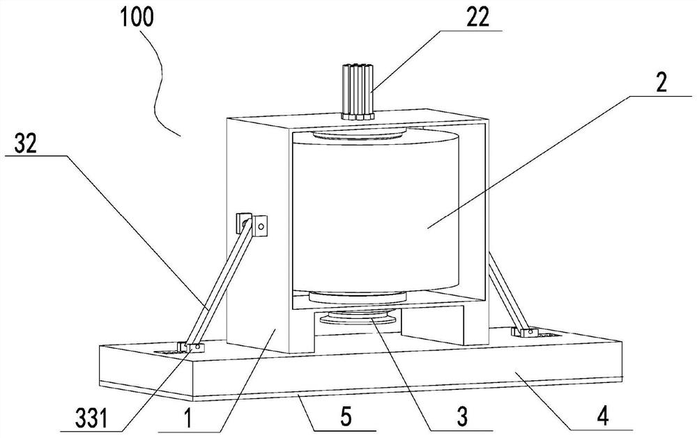
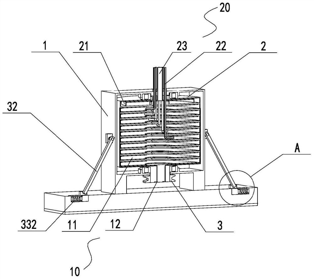
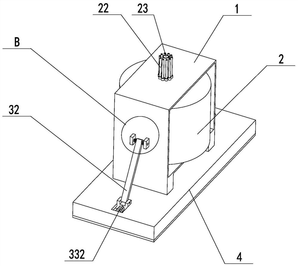
[0004] The object of the present invention is to provide an electrolytic cell, aiming at solving the technical problem in the prior art that the electrolytic cell is pressurized, but the gas precipitation rate cannot be increased, resulting in limited working efficiency of the electrolytic cell

Method used


Image

  • Electrolytic bath
  • Electrolytic bath
  • Electrolytic bath

Examples


Embodiment Construction

[0026] Embodiments of the present invention are described in detail below, examples of which are shown in the drawings, wherein the same or similar reference numerals designate the same or similar elements or elements having the same or similar functions throughout. The embodiments described below by referring to the figures are exemplary and are intended to explain the present invention and should not be construed as limiting the present invention.

[0027] In describing the present invention, it should be understood that the terms "length", "width", "upper", "lower", "front", "rear", "left", "right", "vertical", The orientation or positional relationship indicated by "horizontal", "top", "bottom", "inner", "outer", etc. are based on the orientation or positional relationship shown in the drawings, and are only for the convenience of describing the present invention and simplifying the description, rather than Nothing indicating or implying that a referenced device or element...


PUM


Abstract

The invention relates to the technical field of electrolytic baths, in particular to an electrolytic bath. The rotatable electrolytic cell is supported through the rack and can rotate, the transmission wheel is fixedly connected to the rotatable electrolytic cell and externally connected with the driving device, the driving device drives the transmission wheel to rotate so as to drive the rotatable electrolytic cell to rotate, and the conductive assembly enables the interior of the rotatable electrolytic cell to be powered on. The pipeline assembly is used for inputting electrolyte into the rotatable electrolytic cell and guiding out generated gas while guaranteeing the sealing performance of the rotatable electrolytic cell, then during working, the conductive assembly is used for electrifying the interior of the rotatable electrolytic cell, bubbles of hydrogen and oxygen can be generated, the rotatable electrolytic cell for producing hydrogen is rotated, and a centrifugal force generated by rotation is used for generating oxygen and hydrogen. Pressure difference is produced, separation of gas and electrolyte is accelerated, and the hydrogen production efficiency of the electrolytic cell is improved.

Description

technical field [0001] The invention relates to the technical field of hydrogen production electrolyzers, in particular to an electrolyzer. Background technique [0002] The electrolysis efficiency of the electrolytic cell is directly proportional to the current per unit area and inversely proportional to the number of bubbles in the electrolyte. In order to increase the efficiency of the electrolytic cell, it is necessary to increase the electric current per unit area of ​​the electrolytic cell. As the current increases, the greater the electrolysis rate, the more bubbles will be generated. The electrolyte, the contact area between the electrolyte and the electrolyte, will further reduce the efficiency of hydrogen production, and will eventually reach a dynamic equilibrium point. [0003] At present, the existing technology is to pressurize the electrolyzer to make the volume of the gas of the same mass smaller, and the volume of the bubbles becomes smaller, so that the ef...

Claims


Application Information

Patent Timeline
Patent Type & Authority Applications(China)
IPC IPC(8): C25B9/015C25B1/50C25B1/04C25B9/60C25B9/65C25B15/08
CPCY02E60/36
Inventor 尹泽刘祥瑞
Owner 南京氢灵新能源科技有限公司
Learn More