
Multi-stage compressor and heat pump system

A technology for heat pump systems and compressors, applied to compressors, compressors, irreversible cycle compressors, etc., can solve problems such as narrow operating range, slow feedback speed, and low efficiency, and achieve wide operating range, fast speed change, The effect of fast feedback

Pending Publication Date: 2022-04-15
GUANGDONG MIDEA WHITE HOME APPLIANCE TECH INNOVATION CENT CO LTD +1
View PDF0 Cites 0 Cited by
  • Summary
  • Abstract
  • Description
  • Claims
  • Application Information

AI Technical Summary

Problems solved by technology

The efficiency of this multi-stage compressor is not high, the operating range is narrow, and the feedback speed is slow

Method used


Image

  • Multi-stage compressor and heat pump system
  • Multi-stage compressor and heat pump system
  • Multi-stage compressor and heat pump system

Examples


Embodiment Construction

[0028] The following will clearly and completely describe the technical solutions in the embodiments of the present invention with reference to the accompanying drawings in the embodiments of the present invention. Obviously, the described embodiments are only part of the embodiments of the present invention, not all of them. Based on the embodiments of the present invention, all other embodiments obtained by persons of ordinary skill in the art without creative efforts fall within the protection scope of the present invention.

[0029] It should be noted that all directional indications (such as up, down, left, right, front, back...) in the embodiments of the present invention are only used to explain the relationship between the components in a certain posture (as shown in the accompanying drawings). Relative positional relationship, movement conditions, etc., if the specific posture changes, the directional indication will also change accordingly.

[0030] In addition, in t...


PUM


Abstract

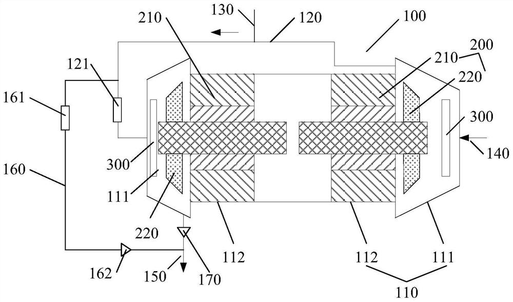
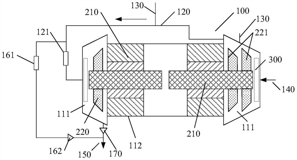
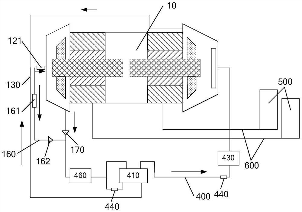
A multi-stage compressor and a heat pump system are provided herein. The multi-stage compressor comprises a shell, the shell comprises N matching areas, each matching area comprises a volute compression cavity and a mounting cavity, the N volute compression cavities are arranged to be N stages, and an outlet of the nth-stage volute compression cavity communicates with an inlet of the (n + 1) th-stage volute compression cavity; the N compression assemblies are installed in the N matching areas in a one-to-one correspondence mode, each compression assembly comprises a motor and a compression impeller in transmission connection with the motor, the motors are located in the installation cavities, and the compression impellers are located in the volute compression cavities; wherein n is a positive integer, N > = 2, and n + 1 < = N. The multi-stage compressor is high in efficiency, wide in operation range and high in feedback adjusting speed.

Description

technical field [0001] The invention relates to the field of electrical equipment, in particular to a multistage compressor and a heat pump system. Background technique [0002] The existing multi-stage compressor includes a casing, a variable frequency motor, a rotating shaft and three compression impellers. The first volute compression cavity, the second volute compression cavity, the installation cavity and the third volute are arranged in sequence in the axial direction of the casing. The casing compression chamber, the frequency conversion motor is located in the installation chamber, and the three compression impellers are located in the first volute compression chamber, the second volute compression chamber and the third volute compression chamber one by one, and the rotating shaft is passed through the three compression impellers and inverter motors. The frequency conversion motor drives the rotating shaft to rotate, and the rotating shaft drives the three compressi...

Claims


Application Information

Patent Timeline
Patent Type & Authority Applications(China)
IPC IPC(8): F04D17/12F04D25/06F04D29/66F25B1/10F25B31/02
Inventor 张运乾胡小文胡斯特
Owner GUANGDONG MIDEA WHITE HOME APPLIANCE TECH INNOVATION CENT CO LTD
Learn More