Bus-controlled pneumatic conveying gulp valve and control system

A technology of pneumatic conveying and bus control, applied in the direction of control valve, valve details, valve device, etc., which can solve the problems such as the inability to monitor the instantaneous pressure field of the pipeline pressure pipeline in real time, the inability to distinguish damaged equipment for maintenance, and the inability to monitor the valve status in real time. , to achieve the effect of flexible and changeable control methods, visualization of valve status, and convenient repair and maintenance.

Pending Publication Date: 2022-04-15
广东汕控环保科技有限公司
View PDF0 Cites 0 Cited by
  • Summary
  • Abstract
  • Description
  • Claims
  • Application Information

AI Technical Summary

Problems solved by technology

Using the above mechanical control method, firstly, because of purely mechanical equipment, the control accuracy is poor, and it is impossible to monitor the status of the valve in real time, and it is impossible to judge the damaged equipment and perform maintenance in time; secondly, it is impossible to monitor the pressure of the transmission pipeline and the instantaneous The pressure field conditions; the third is that once the system is designed, it is difficult to adjust, and the response speed is slow and there is a large delay, the actual scope of application is limited

Method used


Image

  • Bus-controlled pneumatic conveying gulp valve and control system
  • Bus-controlled pneumatic conveying gulp valve and control system
  • Bus-controlled pneumatic conveying gulp valve and control system

Examples


Embodiment Construction

[0026] In order to make the object, technical solution and advantages of the present invention clearer, the present invention will be further described in detail below in conjunction with the accompanying drawings.

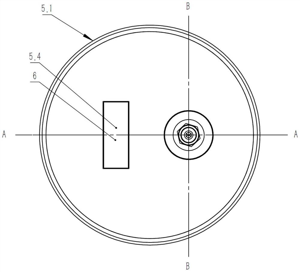
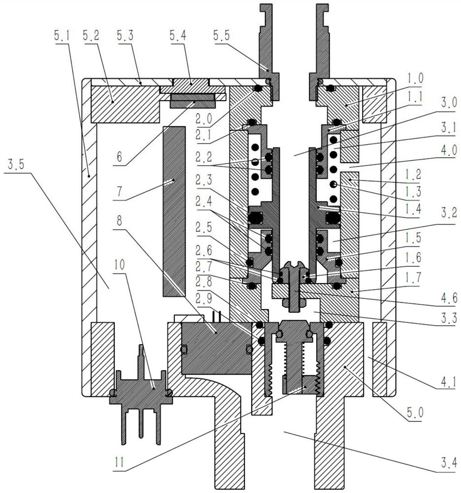
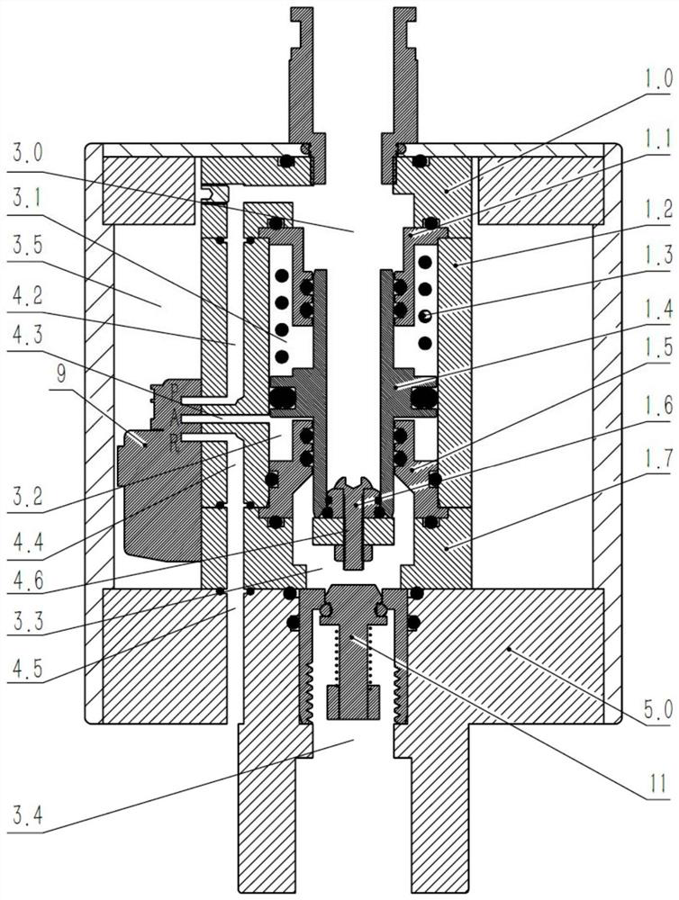
[0027] refer to figure 2 , image 3 As shown, a bus-controlled pneumatic delivery valve 20 includes a valve body, a base 5.0, a housing 5.1, a display screen 6, a central control unit 7, a pressure core 8, and a miniature solenoid valve 9;

[0028] refer to figure 2 As shown, the valve body is arranged on the base 5.0, the housing 5.1 is arranged on the base 5.0, and the upper opening cover of the housing 5.1 is provided with a top plate 5.2, and a top panel 5.3 is fixedly arranged on the top plate, so that the inside of the housing 5.1 forms a shell The inner cavity 3.5, the valve body is arranged on the base 5.0, the upper part of the valve body is connected with the inlet pipe joint 5.5, and the lower part of the base 5.0 is provided with the outlet cavity ...


PUM


Abstract

The bus-controlled pneumatic conveying gulp valve comprises a valve body, a central control unit, a pressure core body and a miniature electromagnetic valve, the valve body comprises an upper valve body, a main valve body and a lower valve body, the upper valve body is arranged at the top of the main valve body, the lower valve body is arranged at the bottom of the main valve body, a hollow piston shaft is arranged in the main valve body, and the piston shaft is arranged in the central control unit. An annular flange is arranged in the middle of the piston shaft in a protruding mode, the piston shaft is movably connected with the interior of the main valve body in an airtight mode through the annular flange, a spring is arranged between the upper valve body and the annular flange, a sealing base is arranged on the lower valve body, and the bottom of the piston shaft is matched with the sealing base in a sealing mode under the action of the spring. The valve can be flexibly controlled to be opened for air supply according to the pressure of a conveying pipeline or a signal on a field bus.

Description

technical field [0001] The invention relates to the technical field of bulk material pipeline pneumatic conveying, in particular to a bus-controlled pneumatic conveying air supplement valve and a control system. Background technique [0002] Pneumatic conveying, also known as airflow conveying, is a conveying technology that uses the energy of airflow to convey granular materials along the direction of airflow in a closed pipeline. It is widely used in thermal power, steel, chemical and metallurgy and other fields. Due to the instability of the characteristics of the bulk material to be transported, or the deviation of the fly ash content between the actual burned coal and the designed coal type, it is easy to cause unstable pneumatic conveying, difficulty in bulk material transportation, and frequent pipe plugging failures. It is more obvious when it is transported over a long distance. [0003] At this stage, in order to reduce pipe plugging and increase system stability,...

Claims


Application Information

Patent Timeline
Patent Type & Authority Applications(China)
IPC IPC(8): F16K37/00F16K31/02F16K31/06F16K15/06F16K15/18
Inventor 林汉标陈晓妹谢英涛麦楚湃
Owner 广东汕控环保科技有限公司
Why Eureka
Try Eureka