Energy-saving incinerator special for chemical industry

An incinerator, chemical technology, applied in the field of energy-saving chemical special incinerators, can solve the problems of energy loss, wasted time, etc., to achieve the effect of improving pulverization and accelerating incineration, accelerating pulverizing and incinerating, and accelerating efficiency

Pending Publication Date: 2022-04-15
刘存孝
View PDF0 Cites 4 Cited by
  • Summary
  • Abstract
  • Description
  • Claims
  • Application Information

AI Technical Summary

Problems solved by technology

[0004] The purpose of the present invention is to provide an energy-saving special incinerator for chemical industry, which has the advantage of automatically adjusting the moving stroke of the crushing mechanism and the auxiliary incineration mechanism, and solves the problem of a large amount of energy loss and wasting a lot of time

Method used


Image

  • Energy-saving incinerator special for chemical industry
  • Energy-saving incinerator special for chemical industry
  • Energy-saving incinerator special for chemical industry

Examples


Embodiment 1

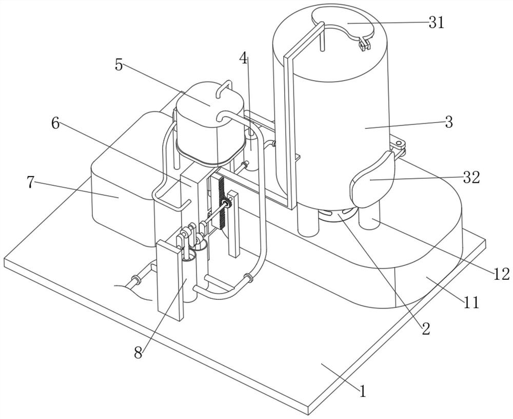
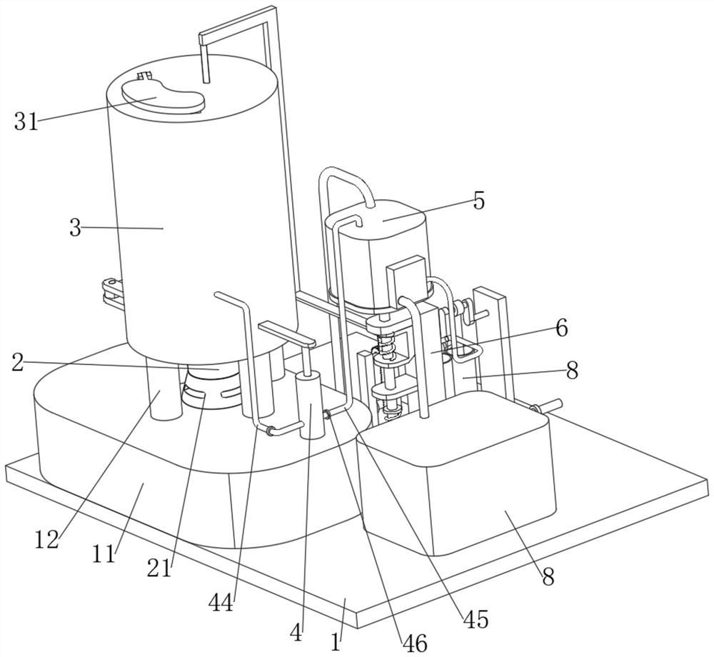
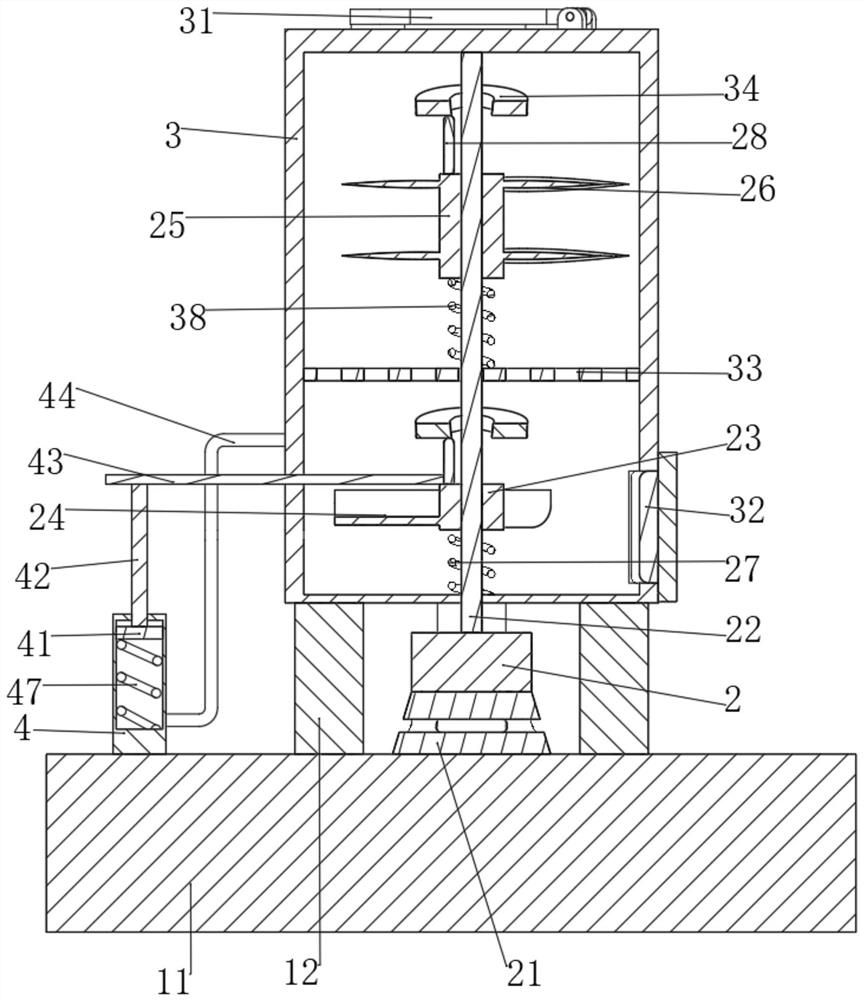
[0032] The present invention provides a technical solution: an energy-saving special incinerator for chemical industry, including a load-bearing plate 1 and a support plate 11, the support plate 11 is fixedly connected to the load-bearing plate 1, and four support columns are fixedly connected to the upper surface of the support plate 11 12. The four supporting columns 12 are fixedly connected with a housing 3, and the housing 3 is provided with a crushing and combustion-supporting mechanism for crushing chemical waste and accelerating the incineration of chemical waste. The upper surface of the housing 3 is provided with a feed port, and the housing 3 The upper surface of the housing 3 is hinged with a feed cover 31 that matches the feed inlet through a pin shaft, and the side of the housing 3 near the support column 12 is provided with a discharge port, and the side of the housing 3 near the support column 12 is hinged with a The discharge cover 32 matched with the discharge ...

Embodiment 2

[0046] It is basically the same as the first embodiment, furthermore, the sliding rod 52 is provided with a replenishing mechanism for replenishing the neutralization tank 5 with alkaline liquid medicine, and the replenishing mechanism includes a The second baffle 64 of the second baffle 64, the end of the sliding rod 52 away from the first baffle 62 is sleeved with a sixth spring 65, and the two ends of the sixth spring 65 are fixedly connected with the second baffle 64 and the support frame 6 respectively, and the sliding frame 61 A rack 9 is fixedly connected to the top, and two support blocks 13 are fixedly connected to the load-bearing plate 1. The opposite surfaces of the two support blocks 13 are fixedly connected to a crankshaft 81 for fixed axis rotation, and a ring 92 is fixedly connected to the arc profile of the crankshaft 81. The circular ring 92 is fixedly connected with multiple sets of cards 93, the circular ring 92 is sleeved with a gear 91, the gear 91 is prov...


PUM


Abstract

The invention discloses an energy-saving chemical industry special incinerator which comprises a bearing plate and a supporting plate, the bearing plate is fixedly connected with the supporting plate, the upper surface of the supporting plate is fixedly connected with four supporting columns, the four supporting columns are fixedly connected with a shell, and the shell is provided with a smashing combustion-supporting mechanism used for smashing chemical industry waste and accelerating incineration of the chemical industry waste. A feeding port is formed in the upper surface of the shell, a feeding cover matched with the feeding port is hinged to the upper surface of the shell through a pin shaft, a discharging port is formed in the side, close to the supporting column, of the shell, a discharging cover matched with the discharging port is hinged to the side, close to the supporting column, of the shell through a pin shaft, and a sieve plate is fixedly connected to the inner wall of the shell. And a neutralizing mechanism for neutralizing sulfide gas generated by incineration is arranged on the supporting plate. According to the crushing and incineration device, through cooperation of the overall structure, the crushing and incineration efficiency is improved, and the effect of purifying generated hydrogen sulfide gas is achieved.

Description

technical field [0001] The invention relates to the technical field of chemical incinerators, in particular to a special energy-saving chemical incinerator. Background technique [0002] The incinerator is a kind of chemical equipment used to incinerate combustible chemical waste. After the incinerated chemical waste is discharged, it will effectively reduce the pollution to the environment. [0003] At present, most of the chemical incinerator crushing mechanism and auxiliary incineration mechanism are fixed equipment, and will not adjust the moving stroke of the crushing mechanism and auxiliary incineration mechanism according to the amount of chemical waste remaining, resulting in a large amount of energy loss and wasting a lot of energy. Time, so we need an energy-saving chemical special incinerator to solve the above problems. Contents of the invention [0004] The purpose of the present invention is to provide an energy-saving special incinerator for chemical indust...

Claims


Application Information

Patent Timeline
Patent Type & Authority Applications(China)
IPC IPC(8): F23G5/033F23G5/28F23G5/44
Inventor 刘存孝
Owner 刘存孝
Why Eureka
Try Eureka