Cavity with air pressure measuring function
An air pressure measurement and cavity technology, which is applied in the direction of measuring fluid pressure, measuring fluid pressure through mechanical components, measuring devices, etc., can solve problems such as inconvenience in use, and achieve the effect of high air pressure detection sensitivity and convenient use.
- Summary
- Abstract
- Description
- Claims
- Application Information
AI Technical Summary
Problems solved by technology
Method used
Image

Examples
Embodiment 1
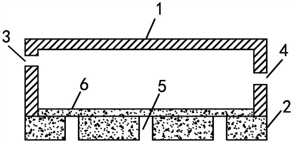
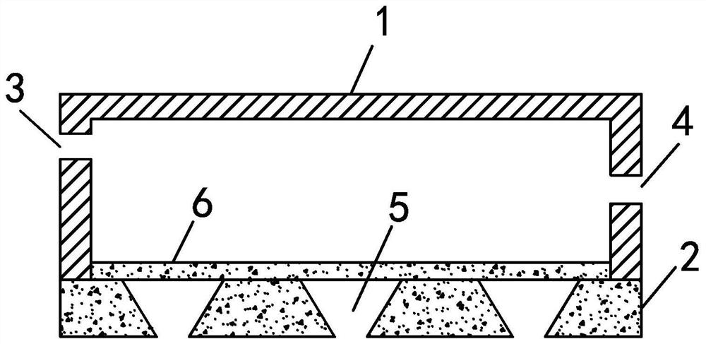
[0019] The invention provides a cavity with air pressure measurement function. Such as figure 1 As shown, the chamber with air pressure measurement function includes a chamber wall 1 , a measurement window, an air inlet 3 , and an air outlet 4 . The cavity wall 1 is made of stainless steel. Further, the material of cavity wall 1 is 300 series stainless steel, which is a low-carbon steel containing Cr, which has the advantages of excellent corrosion resistance, high yield, non-magnetic, good welding performance, low electrical conductivity and thermal conductivity, etc. , able to work in a wide temperature range. The chamber wall 1 and the measurement window part enclose a chamber. That is to say, one piece will be provided as the measurement window portion on the entire cavity wall 1 . The air inlet 3 and the air outlet 4 are arranged on the chamber wall 1 . The air inlet 3 and the air outlet 4 do not face the silicon membrane 6, so as to prevent the flowing gas from affe...
Embodiment 2
[0022] On the basis of Example 1, the hole 5 is in the shape of a truncated cone, and the hole 5 is thicker on the inner side of the cavity; the hole 5 is thinner on the outer side of the cavity. In this way, the contact area between the silicon film 6 and the hole 5 is larger, and the hole 5 hinders the silicon film 6 less. 5 protrudes more, thereby changing the shape and size of the resonant cavity more, thereby changing the position of the resonant wavelength and the intensity of reflected light more, thereby achieving higher sensitivity air pressure detection. In this embodiment, air pressure detection can be realized by measuring the shift of resonance wavelength and the intensity of reflected light, which improves the accuracy of air pressure detection.
[0023] In this embodiment, when the silicon film 6 protrudes toward the hole 5, small-sized slits are formed between the silicon film 6 and the sidewall of the hole 5, and these small-sized slits can localize the incide...
Embodiment 3
[0026] On the basis of Example 2, the silicon film 6 is thinner at the center of the hole 5 and thicker at the edge of the hole 5 . That is to say, the thickness of the silicon film 6 is not uniform: at the hole 5, the silicon film 6 is thin, especially in the middle of the hole 5; on the silicon layer 5, the silicon film 6 is thick. In this way, the silicon film 6 can be firmly attached or adhered to the silicon layer 2; under the action of air pressure, the silicon film 6 can protrude more into the hole 5, especially at the center of the hole 5. , the silicon film 6 protrudes more into the hole 5, thereby changing the shape of the resonant cavity on the side of the silicon film 6 more, and also changing the size of the resonant cavity, thereby changing the resonant wavelength of the resonant cavity more And reflectance spectrum, so as to realize the detection of air pressure with higher sensitivity.
PUM
| Property | Measurement | Unit |
|---|---|---|
| thickness | aaaaa | aaaaa |
| thickness | aaaaa | aaaaa |
| diameter | aaaaa | aaaaa |
Abstract
Description
Claims
Application Information
 - R&D
- Intellectual Property
- Life Sciences
- Materials
- Tech Scout
- Unparalleled Data Quality
- Higher Quality Content
- 60% Fewer Hallucinations
Browse by: Latest US Patents, China's latest patents, Technical Efficacy Thesaurus, Application Domain, Technology Topic, Popular Technical Reports.
© 2025 PatSnap. All rights reserved.Legal|Privacy policy|Modern Slavery Act Transparency Statement|Sitemap|About US| Contact US: help@patsnap.com