
LCD liquid crystal screen cutting and packaging process

A packaging process and liquid crystal screen technology, which is applied in the direction of assembling printed circuits, optics, instruments, etc., can solve the problems of insufficient flexibility, inability to locate the screen, single protective structure of the cutting table, etc., so as to avoid cleaning difficulties and increase The effect of flexibility

Pending Publication Date: 2022-04-15
苏州视达讯远电子科技有限公司
View PDF2 Cites 0 Cited by
  • Summary
  • Abstract
  • Description
  • Claims
  • Application Information

AI Technical Summary

Problems solved by technology

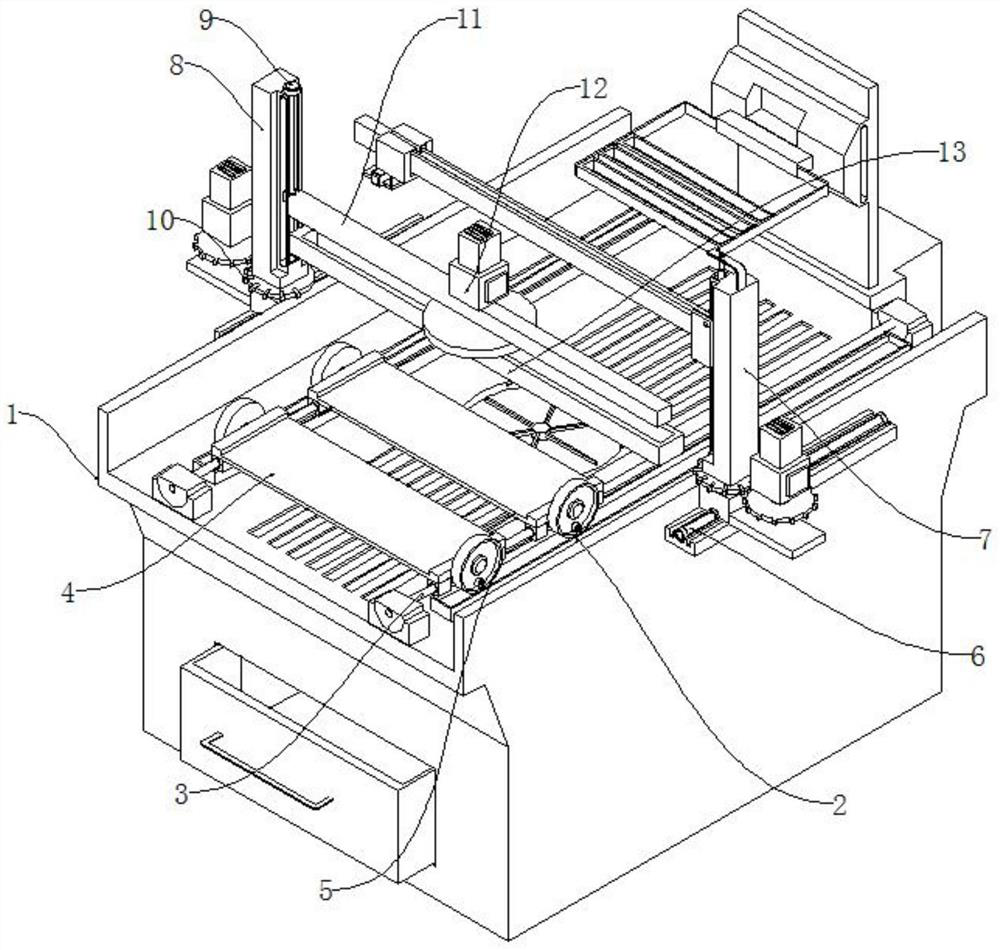
[0006] In order to overcome the above-mentioned defects of the prior art, an embodiment of the present invention provides an LCD liquid crystal screen cutting and packaging process to solve the problem in the above-mentioned background technology that the fixation of the screen is not stable enough in actual use, and it is easy to be damaged during the cutting process. It causes substantial damage to the screen, and it is difficult to control the cutting force of the screen, which makes the cutting of the screen prone to crack extension. The protection structure is relatively simple and the flexibility is insufficient

Method used


Image

  • LCD liquid crystal screen cutting and packaging process
  • LCD liquid crystal screen cutting and packaging process
  • LCD liquid crystal screen cutting and packaging process

Examples


Embodiment Construction

[0039] The following will clearly and completely describe the technical solutions in the embodiments of the present invention with reference to the accompanying drawings in the embodiments of the present invention. Obviously, the described embodiments are only some, not all, embodiments of the present invention. Based on the embodiments of the present invention, all other embodiments obtained by persons of ordinary skill in the art without making creative efforts belong to the protection scope of the present invention.

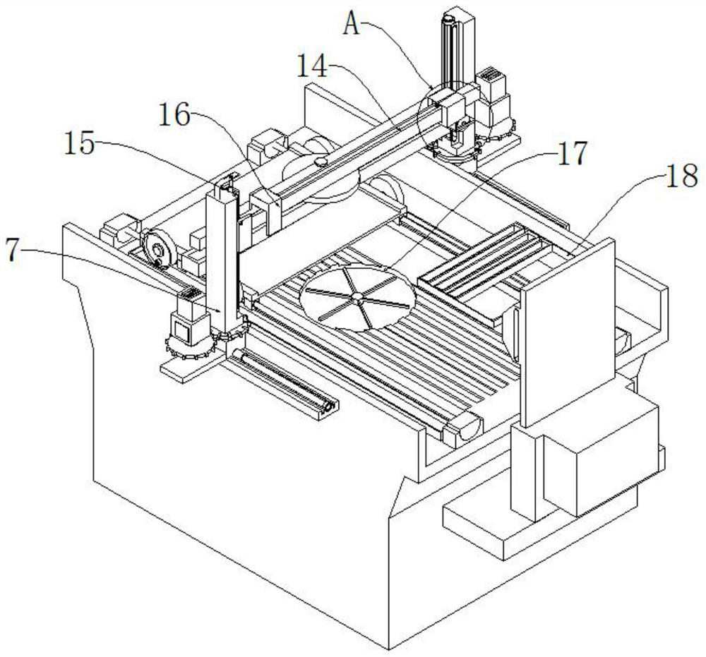
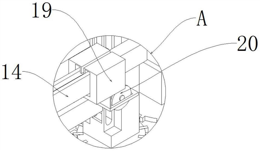
[0040] according to Figure 1-11 An LCD liquid crystal screen cutting and packaging process shown specifically includes the following steps:

[0041] S1: Place the LCD liquid crystal screen after a series of processing on the positioning carrier 4 above the inner side of the cutting table 1 stably, and use the deck 402 on the positioning carrier 4 to clamp and fix the screen left and right;

[0042] S2: Use the first driving screw 3 to move the positioning ca...


PUM


Abstract

The invention discloses a liquid crystal display (LCD) cutting and packaging process, and particularly relates to the related technical field of LCDs, and the LCD cutting and packaging process comprises the following steps: S1, stably placing a series of processed LCDs on a positioning carrier plate above the inner side of a cutting table; s2, an electric cutting machine is aligned with the starting end of the marked cutting line; and S3, continuously moving the positioning carrier plate to the position of the mounting rack, adjusting the left-right position of the spot welding machine by using a bidirectional screw rod, pasting the pasted element on the bonding pad printed with the soldering paste, and packaging and connecting the circuit board and the outer lead of the liquid crystal screen device by using a conductive adhesive. The spot welding machine is combined with the two-way lead screw, the left-right position of the spot welding machine is adjusted through the two-way lead screw, the spot welding machine can flexibly conduct lead welding on a circuit board behind an LCD screen, the worm wheel is matched with the worm, the direction of force can be changed through the worm, the worm wheel drives the worm to move up and down, and the welding precision is improved. Therefore, the height of the spot welding needle is controlled.

Description

technical field [0001] The present invention relates to the technical field related to LCD liquid crystal screens, and more specifically, the present invention relates to a cutting and packaging process of LCD liquid crystal screens. Background technique [0002] The LCD liquid crystal screen is one of the commonly used display screens in the screen, but it has certain differences from the LED screen. Display images, and LED screens use light-emitting diodes to display images. There is an essential difference between the two. The overall clarity and resolution of LCD liquid crystal screens are low, but they are often used for information playback in public places. Among them, in high-speed rail And on the subway, LCD screens are often seen. [0003] The Chinese patent application publication number CN113514970A discloses a substrate cutting and processing device for liquid crystal screens, which includes a bottom support platform for placing glass substrates. The key point...

Claims


Application Information

Patent Timeline
IPC IPC(8): G02F1/13G02F1/1333H05K3/34
Inventor 杨秀培佟夫于庆安
Owner 苏州视达讯远电子科技有限公司
Learn More