
Magnetic head manufacturing and mainboard assembling method for equivalently replacing surface mounting and magnetic head

A surface mount, magnetic head technology, applied in the direction of assembling printed circuits, instruments, inductive recording carriers, etc. with electrical components, can solve the problem of difficulty in meeting the coplanarity requirements of the bottom edge of the magnetic head shell, poor welding of pins, shells and motherboard pads, etc. Affect the service life of the machine and other problems, to achieve the effect of saving manufacturing costs, small flatness, and improving service life

Pending Publication Date: 2022-04-15
APOLLO ZHUHAI ELECTRONICS
View PDF0 Cites 0 Cited by
  • Summary
  • Abstract
  • Description
  • Claims
  • Application Information

AI Technical Summary

Problems solved by technology

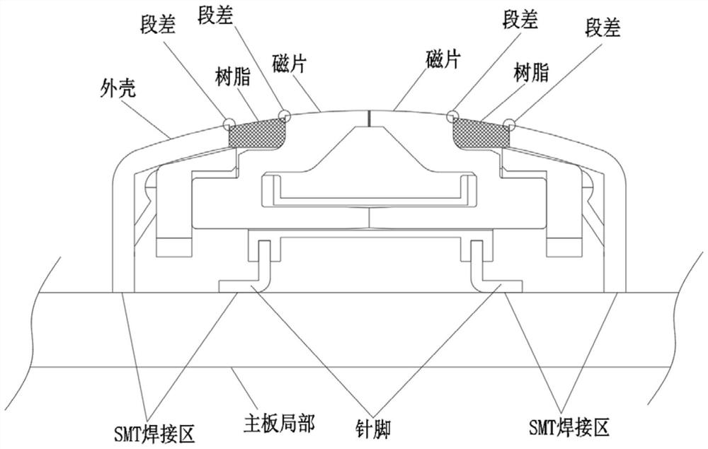
[0005] 2. If the surface mount magnetic head is soldered to the motherboard pad by only 6 pins, it will easily cause service life problems. The bottom edge of the shell must be welded to the motherboard at the same time to improve welding reliability and increase the service life of the motherboard.
The current ordinary manufacturing process is difficult to meet the coplanarity requirements between the pins of the magnetic head and the bottom edge of the housing. Even if the coplanarity requirements are met, the cost will be high
If the coplanarity cannot meet the requirements, after the magnetic head is welded by SMT, some pins, shells and motherboard pads will be poorly welded, which will affect the service life of the machine
[0006] Therefore, from figure 1 It can be seen that the pins of the magnetic head and the bottom of the shell are in contact with the motherboard pads, so the magnetic head that meets the surface mount (SMT) welding method is a product with complicated manufacturing process and high cost, and the application method of welding to the motherboard by SMT method is also relatively Complicated, none meet cost requirements

Method used


Image

  • Magnetic head manufacturing and mainboard assembling method for equivalently replacing surface mounting and magnetic head
  • Magnetic head manufacturing and mainboard assembling method for equivalently replacing surface mounting and magnetic head
  • Magnetic head manufacturing and mainboard assembling method for equivalently replacing surface mounting and magnetic head

Examples


Embodiment Construction

[0038] In order to make the purpose, technical solutions and advantages of the embodiments of the present invention more clear, the following will clearly and completely describe the technical solutions of the embodiments of the present invention in conjunction with the drawings of the embodiments of the present invention. Apparently, the described embodiments are some, not all, embodiments of the present invention. Based on the described embodiments of the present invention, all other embodiments obtained by persons of ordinary skill in the art without creative efforts shall fall within the protection scope of the present invention.

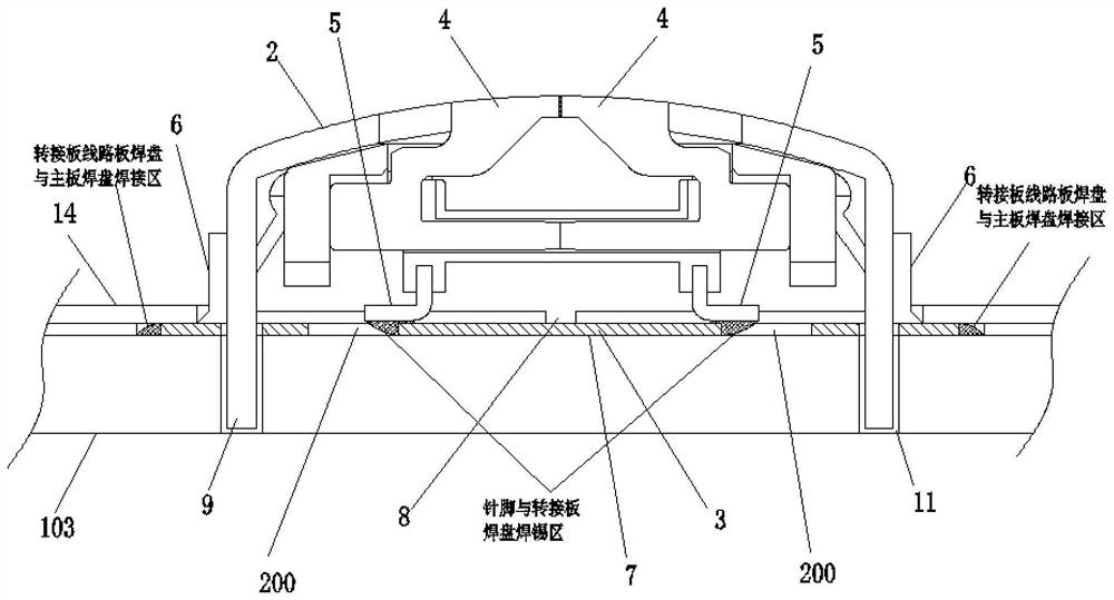
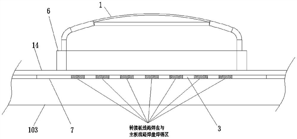
[0039] see figure 2 and image 3 , when carrying out a kind of magnetic head manufacturing and motherboard assembly method of equivalent replacement surface mount of the present invention, the present invention provides a kind of magnetic head that is used for equivalent magnetic head surface mounting, and this magnetic head comprises: magneti...


PUM


Abstract

The invention provides a magnetic head manufacturing and mainboard assembling method for equivalently replacing surface mounting and a magnetic head, and the method comprises the steps: carrying out the automatic welding of a magnetic head pin and a bonding pad of a switching circuit board, sleeving a silica gel sealing ring on an outer frame of a magnetic head housing, injecting glue into the magnetic head from a glue injection hole of the switching circuit board, and carrying out the packaging. A double-sided gum insulation sheet is pasted on the surface of the switching circuit board to form a magnetic head which equivalently replaces surface mounting; the magnetic head is assembled on a main board of the card reading equipment, the bonding pads of the switching circuit board are welded with the bonding pads of the main board in a one-to-one correspondence manner in an automatic manner, and a metal safety board with insulating films on two sides is assembled on the silica gel sealing ring outer frame of the magnetic head, so that the magnetic head and the main board can be assembled. The method can avoid the influence of the high temperature of a reflow oven on the resin in the magnetic head to cause segment difference, does not need to require higher welding pin flatness according to SMT parts, and has the purposes of long service life, good welding firmness, high working efficiency, low magnetic head manufacturing cost and the like.

Description

technical field [0001] The invention relates to the technical field of electronic products, in particular to a magnetic head manufacturing and motherboard assembly method and a magnetic head which are equivalent to replace surface mounting. Background technique [0002] As a magnetic information reading and writing component, the magnetic head needs to be installed on the main board in the machine equipment, and it can be connected with the main board circuit to realize the reading and writing function. The existing surface mount (SMT) magnetic head can complete the SMT surface mount welding with the main board through reflow soldering. The corresponding pads correspond to the head pad pins and the bottom surface of the case. Such as figure 1 as shown, figure 1 It shows the main structure of the surface mount magnetic head and the structure after SMT welding with the main board. [0003] In actual production and real-world applications, existing surface mount magnetic he...

Claims


Application Information

Patent Timeline
Patent Type & Authority Applications(China)
IPC IPC(8): H05K3/32H05K3/34G06K7/08
Inventor 杨永祥白鸿璋李幼生
Owner APOLLO ZHUHAI ELECTRONICS
Learn More