
Wet cooling tower

A wet cooling and tower body technology, applied in the field of cooling towers, can solve the problems of easy dust collection, regular cleaning, and large resistance of finned tubes, and achieve the effects of simple installation, high electrothermal conversion rate, and improved fog elimination efficiency

Pending Publication Date: 2022-04-19
江苏丰泰节能环保科技有限公司
View PDF0 Cites 0 Cited by
  • Summary
  • Abstract
  • Description
  • Claims
  • Application Information

AI Technical Summary

Problems solved by technology

However, there are certain defects in both technologies. The fin tube type defogging has higher requirements on the space height of the cooling tower, and the water pump head needs to be increased, which increases the energy consumption of the cooling tower. The defogging process is more complicated, and the louver system and Vacuum pumping system; the surface of finned tubes is easy to collect dust, which affects the heat transfer effect and needs to be cleaned regularly; it is only suitable for new projects and cannot be modified for the original cooling tower
Condensing modular defogging has certain requirements on the height of the air chamber, and a certain pump head needs to be increased. Its biggest disadvantage is that the resistance is relatively large, especially in summer when the defogging is not used. The resistance will increase the energy consumption of the cooling tower, thereby increasing the cooling capacity. The long-term operation cost of the tower; the fog elimination process is relatively complicated, and the shutters on the outer wall and the flap system at the lower part of the module need to be adjusted; it is only suitable for new projects, and cannot be modified for the original cooling tower

Method used


Image

  • Wet cooling tower
  • Wet cooling tower

Examples


Embodiment 1

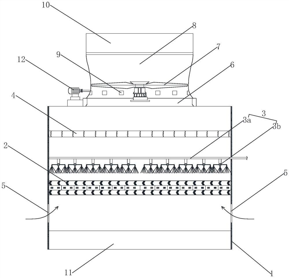
[0019] like figure 1 As shown, a wet cooling tower includes a tower body 1, a packing layer 2, a spray device 3 and a water receiver 4 are arranged in the tower body 1 sequentially from bottom to top, and the spray device 3 includes a spray pipe 3a and several The nozzle 3b connected with the spray pipe 3a, the tower wall below the packing layer 2 is provided with an air inlet 5, the top of the tower body 1 is provided with an air outlet 6, and the bottom of the tower body 1 is provided with a sump 11, the sump 11 is located at the entrance Below the tuyere 5, the air outlet 6 is provided with a fan 7, the fan 7 is driven by a motor 12, the fan 7 is located in the air cylinder 8, and the top of the air cylinder 8 is provided with an air exhaust port 10. The structures of the above-mentioned wet cooling towers are existing There are technologies, so I won't go into details here. The electrothermal film 9 is evenly arranged on the outer circumferential wall or the inner circumf...

Embodiment 2

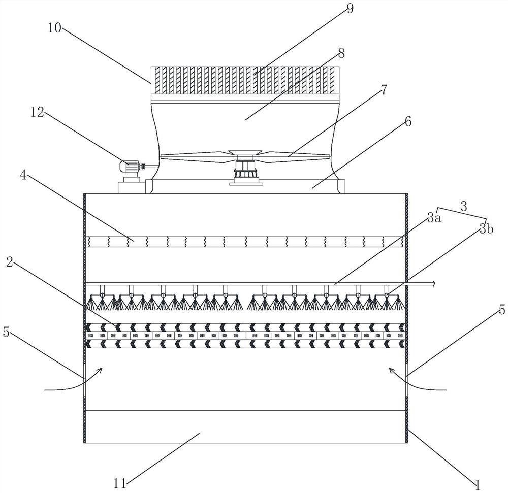
[0022] like figure 2 As shown, the structure of the wet cooling tower is the same as that of Embodiment 1, except that the electrothermal film 9 is arranged at the air outlet 10 above the air cylinder 8 instead of the bottom of the air cylinder 8 .

[0023] The working principle of this embodiment is: the circulating hot water is distributed to several nozzles 3b through the spray pipe 3a, sprayed evenly on the packing layer 2 through the several nozzles 3b, and the sprayed hot water forms a thin film on the packing layer 2. Under the suction of the fan 7, the dry and cold air outside the tower enters the tower from the air inlet 5 to exchange heat with the packing layer 2. The sprayed hot water evaporates and cools to become cold water and enters the sump 11. The dry and cold air in the tower passes through the packing layer 2 and the packing layer 2. After spraying hot water for heat exchange, the saturated hot and humid air continues to rise, and the water droplets formed ...


PUM


Abstract

The invention relates to the technical field of cooling towers, in particular to a wet-type cooling tower which comprises a tower body, a filler layer, a spraying device and a water collector are sequentially arranged in the tower body from bottom to top, an air inlet is formed in the tower wall below the filler layer, an air outlet is formed in the top of the tower body, a fan is arranged at the air outlet and arranged in an air duct, and the water collector is arranged in the air duct. An electrothermal film is arranged above the water collector and is used for demisting; the fog dispersal device is simple in structural design, small in occupied space, low in energy consumption, high in fog dispersal efficiency and long in service life.

Description

technical field [0001] The invention relates to the technical field of cooling towers, in particular to a wet cooling tower. Background technique [0002] The cooling tower is a device that uses water as a circulating coolant to absorb heat from the system and discharge it to the atmosphere to reduce the water temperature; it uses water and air to exchange heat and cold to generate steam, and the steam volatilizes to take away heat to achieve evaporation and heat dissipation. The principle of convective heat transfer and radiation heat transfer is used to dissipate the waste heat generated in industry or in refrigeration and air conditioning to reduce the water temperature of the evaporative cooling device to ensure the normal operation of the system. Cooling towers are divided into wet cooling towers, dry cooling towers and wet and dry cooling towers according to the contact mode of water and air. [0003] When the temperature is low in winter, the water vapor discharged f...

Claims


Application Information

Patent Timeline
IPC IPC(8): F28C1/16
CPCF28C1/16
Inventor 殷国平袁亮
Owner 江苏丰泰节能环保科技有限公司
Features
  • Generate Ideas
  • Intellectual Property
  • Life Sciences
  • Materials
  • Tech Scout
  • Unparalleled Data Quality
  • Higher Quality Content
  • 60% Fewer Hallucinations
Learn More