Large-scale multiple-input multiple-output channel simulation method and device based on optical matrix switching

A channel simulation, multiple-input and multiple-output technology, applied in the field of communication transmission, can solve the problems that the signal transmitting equipment cannot be easily moved, the time-frequency system cannot be synchronized and unified, and the parallel expansion of multiple channels is not supported.

Active Publication Date: 2022-04-19
NAT UNIV OF DEFENSE TECH
View PDF14 Cites 1 Cited by
  • Summary
  • Abstract
  • Description
  • Claims
  • Application Information

AI Technical Summary

Problems solved by technology

[0003] Ordinary single-level channel simulation equipment can only support wired channels, such as 4 or 8 channels, and because the simulation data drive control is relatively independent, the time-frequency system cannot be synchronized and unified, and does not support multi-channel parallel expansion, and considering some signal transmission equipment, Signal forwarding equipment, signal receiving equipment, etc. are limited by volume, weight, installation status, inability to move easily (such as large ground base stations, assembled satellites, etc.), and physical distance between each other (hundreds of meters or even thousands of kilometers). The signal interconnection of ordinary stand-alone-level channel simulation equipment is basically difficult, so that it cannot support the large-scale multiple-input multiple-output channel simulation required for the internal docking test of a large-scale system

Method used


Image

  • Large-scale multiple-input multiple-output channel simulation method and device based on optical matrix switching
  • Large-scale multiple-input multiple-output channel simulation method and device based on optical matrix switching
  • Large-scale multiple-input multiple-output channel simulation method and device based on optical matrix switching

Examples


Embodiment Construction

[0045] In order to make the purpose, technical solutions and advantages of the embodiments of the present invention clearer, the technical solutions in the embodiments of the present invention will be clearly and completely described below in conjunction with the drawings in the embodiments of the present invention. Obviously, the described embodiments It is only some embodiments of the present invention, but not all embodiments. Based on the embodiments of the present invention, all other embodiments obtained by persons of ordinary skill in the art without making creative efforts belong to the protection scope of the present invention.

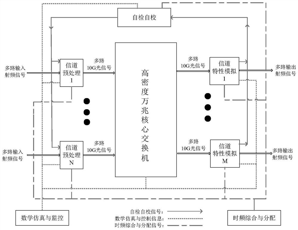
[0046] The first aspect of the present invention discloses a large-scale MIMO channel simulation method based on optical matrix switching, and the method is realized based on a large-scale MIMO channel simulation system. figure 1 It is a schematic diagram of a large-scale MIMO channel simulation system according to an embodiment of the presen...


PUM


Abstract

The invention provides a large-scale multi-input multi-output channel simulation method and device based on optical matrix switching. The method is realized based on a large-scale multiple-input multiple-output channel simulation system, and the large-scale multiple-input multiple-output channel simulation system comprises a plurality of channel preprocessing subsystems, an optical switching subsystem, a plurality of channel characteristic simulation subsystems, a self-checking and self-correcting subsystem, a mathematical simulation and monitoring subsystem and a time-frequency synthesis and distribution subsystem. The subsystems are connected through various optical fibers to achieve interconnection and intercommunication, are used for transmitting high-speed data signals, communication information, control instructions, frequency, pulses, time signals and the like, and have the capability of centralized-distributed arrangement of various devices in the system based on optical fiber signal long-distance transmission. And the large-scale parallel expansion capability of the number of system signal input and output links is realized.

Description

technical field [0001] The invention belongs to the technical field of communication transmission, and in particular relates to a large-scale multiple-input multiple-output channel simulation method and device based on optical matrix switching. Background technique [0002] Communication, radar, electronic countermeasures and other large-scale radio systems or large-scale signal docking scenarios include a variety of signal transmitting equipment, signal forwarding equipment, signal receiving equipment and other wireless signal receiving and processing equipment, the radio frequency signal will be introduced during the space transmission process The dynamic characteristics and environmental channel (including such as ionosphere, troposphere, multipath effect, shadowing effect, etc.) characteristics generated by relative motion between platforms cause real-time changes in signal power, frequency, phase, delay and other characteristics. Then, before the actual operation of the...

Claims


Application Information

Patent Timeline
Patent Type & Authority Applications(China)
IPC IPC(8): H04B17/391H04B7/0413H04B10/27
CPCH04B17/3912H04B7/0413H04B10/27Y02D30/70
Inventor 李蓬蓬肖志斌李柏渝左勇吕志成王飞雪刘文祥陈雷黄新明谢名赞刘欢钟水彬
Owner NAT UNIV OF DEFENSE TECH
Why Eureka
Try Eureka