
System and method for vehicle diagnostic wake-up

A vehicle system and controller technology, applied in chemical instruments and methods, registration/indication of vehicle operation, separation methods, etc., can solve problems such as high power consumption, reduce the possibility of system deterioration, and reduce unnecessary consumption. Effect

Pending Publication Date: 2022-04-22
FORD GLOBAL TECH LLC
View PDF0 Cites 0 Cited by
  • Summary
  • Abstract
  • Description
  • Claims
  • Application Information

AI Technical Summary

Problems solved by technology

However, maintaining the controller active until such a condition occurs can consume significant power

Method used


Image

  • System and method for vehicle diagnostic wake-up
  • System and method for vehicle diagnostic wake-up
  • System and method for vehicle diagnostic wake-up

Examples


Embodiment Construction

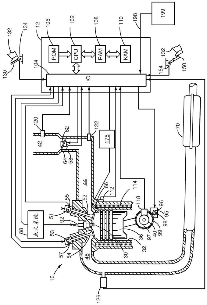
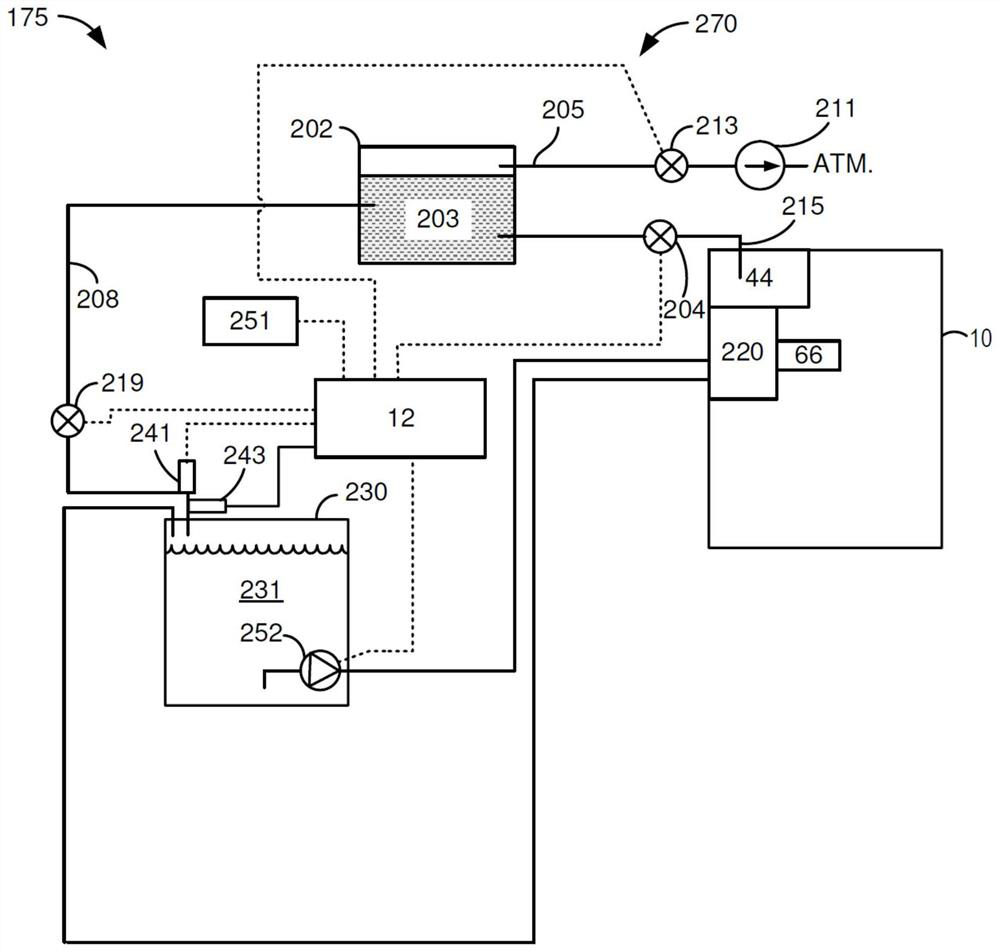
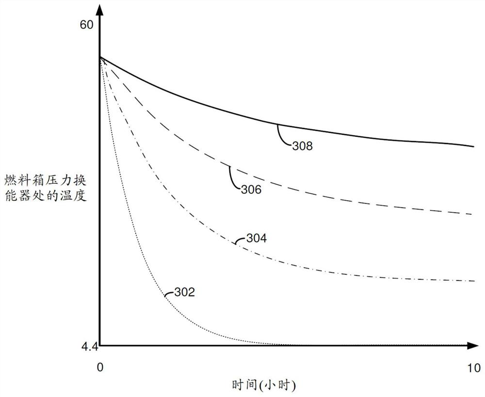
[0014] This instruction pertains to activating or waking up the controller from sleep mode to perform evaporative emissions system diagnostics. While in sleep mode, the controller can consume a small fraction of the power it consumes during fully active operation. Accordingly, the controller may operate in a sleep mode when limited controller operation is required to conserve power. However, the controller can wake up to perform diagnostics appropriate for quiet vehicle conditions. For example, the controller may wake up to perform a leak test or diagnostic of the evaporative emissions system. If the controller wakes up under conditions where it is not expected to perform a leak test, the battery's power may be wasted. figure 1 The engine system is shown in, and figure 2 An evaporative emissions system is shown in , which may be included in a vehicle with the engine. image 3 The evaporative emission system cooling curve is shown. Figure 4 An example controller wake and...


PUM


Abstract

The invention provides a system and method for vehicle diagnostic wake-up. Systems and methods for waking up a controller from a sleep mode are described. In one example, the controller may be awakened in response to an estimated amount of time required for a temperature in the evaporative emission system to be within a threshold temperature of an ambient temperature.

Description

technical field [0001] The present invention relates to methods and systems for waking up a vehicle controller for diagnostic purposes after the vehicle has been shut down. The method can predict when in the future it is appropriate to perform a diagnosis. Background technique [0002] Vehicles may be equipped with evaporative emissions systems for reducing the amount of fuel vapors that may escape from the vehicle. The evaporative emission system may be tested from time to time to ensure the desired level of operation. In particular, leak diagnosis of the evaporative emissions system may be started after the vehicle's engine has been stopped. The diagnosis may be more reliable if the evaporative emission system is evaluated under "quiet" conditions. Quiet conditions reduce system noise, thereby reducing the likelihood of false positive indications of system problems. The system may be quietest when the temperature in the evaporative emissions system is within a threshol...

Claims


Application Information

Patent Timeline
Patent Type & Authority Applications(China)
IPC IPC(8): F02D29/02F02M25/08
CPCF02D29/02F02M25/08F02M25/0809G06F1/3203G06F1/3243G06F1/3296F02D2200/0414F02D2200/70F02D41/04F02D2200/0416F02D2250/12F02D41/003Y02D10/00G07C5/0808B01D2259/4516B01D53/0415
Inventor 罗伯特·詹茨萨尼亚姆·夏尔马M·卡彭特艾德·杜道尔
Owner FORD GLOBAL TECH LLC
Features
  • Generate Ideas
  • Intellectual Property
  • Life Sciences
  • Materials
  • Tech Scout
  • Unparalleled Data Quality
  • Higher Quality Content
  • 60% Fewer Hallucinations
Learn More