Quasi-dynamic vehicle-bridge aerodynamic characteristic wind tunnel test device

A technology of wind tunnel test and aerodynamic characteristics, which is applied in the field of wind tunnel test, can solve the problems that are difficult to apply to high-speed train-bridge aerodynamic characteristics test, and achieve the effects of avoiding force measurement noise interference, wide application range, and avoiding mutual influence

Active Publication Date: 2022-04-22
SOUTHWEST JIAOTONG UNIV
View PDF18 Cites 1 Cited by
  • Summary
  • Abstract
  • Description
  • Claims
  • Application Information

AI Technical Summary

Problems solved by technology

Therefore, the existing wind tunnel test methods are difficult to a

Method used


Image

  • Quasi-dynamic vehicle-bridge aerodynamic characteristic wind tunnel test device
  • Quasi-dynamic vehicle-bridge aerodynamic characteristic wind tunnel test device
  • Quasi-dynamic vehicle-bridge aerodynamic characteristic wind tunnel test device

Examples


Embodiment 1

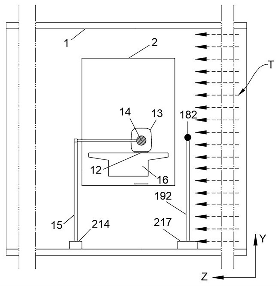
[0029] It is mainly aimed at the structural schematic diagram of the whole device when the vehicle model 13 is a wheel-rail train. Wherein, the wheel-rail train described in the embodiment of the present application refers to the form of railway train that utilizes the interaction between the wheel and the rail to realize the support and guidance of the vehicle on the track, such as the current Harmony and Fuxing EMUs in my country Wait.

[0030] Such as Figure 1 ~ Figure 3 As shown, a pseudo-dynamic vehicle-bridge aerodynamic wind tunnel test device described in the embodiment of the present application includes a fan 3, a wind tunnel 1, a bridge model 16, a vehicle model 13, a speedometer and a dynamometer.

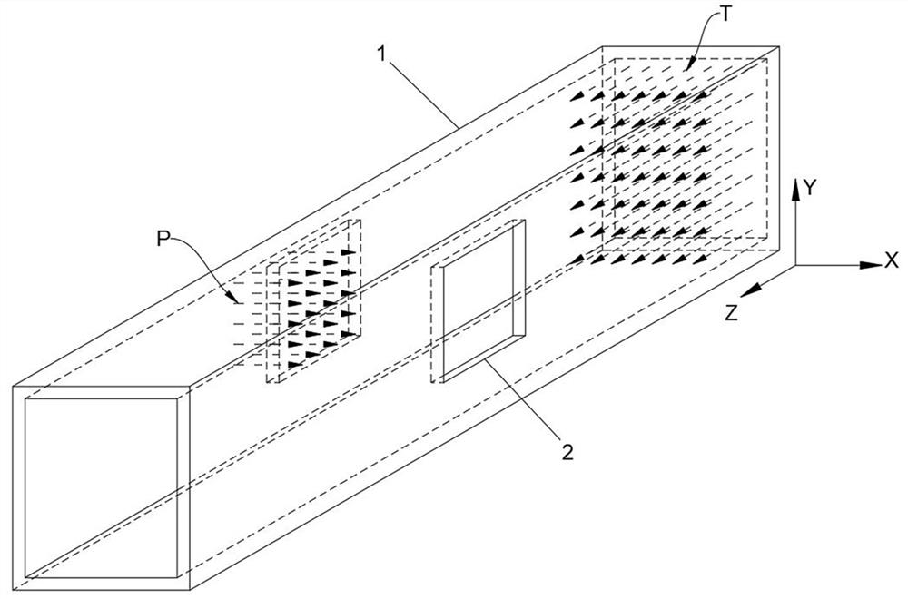
[0031] In the embodiment of this application, such as figure 1 and Figure 7 As shown, the width direction of the wind tunnel 1 (ie figure 1 and Figure 7 There are openings 2 at both ends in the direction indicated by the middle X-axis, and the openings 2 are used...

Embodiment 2

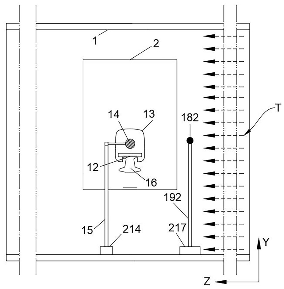
[0061] Such as Figure 4 ~ Figure 6 As shown, another pseudo-dynamic vehicle-bridge aerodynamic wind tunnel test device described in the embodiment of the present application is mainly aimed at the structural schematic diagram of the entire device when the vehicle model 13 is a maglev train. Wherein, the maglev train described in the embodiment of the present application refers to a conventional high-speed maglev train, which uses electromagnetic attraction to realize the suspension and guidance between the vehicle and the track, and there is no contact between the train tracks. For example, the TR08 train on the Shanghai maglev train demonstration operation line in China, and the 600km / h high-speed magnetic train that will roll off the assembly line in Qingdao in 2021.

[0062] Embodiment 2 is substantially the same as Embodiment 1 in terms of structural arrangement, except that: the specific form of the vehicle model 13 is different; the specific form of the bridge model 16 ...


PUM


Abstract

The invention relates to the technical field of wind tunnel tests, and particularly discloses a quasi-dynamic vehicle-bridge aerodynamic characteristic wind tunnel test device, which comprises a fan, a wind tunnel, a bridge model, a vehicle model, a tachymeter and a dynamometer, wherein the bridge model is arranged in a wind tunnel, and the vehicle model is arranged above the bridge model and located in the wind tunnel; the tachymeter is arranged between the fan and the wind tunnel; the dynamometer is installed on the vehicle model. The fan is arranged at one end of the wind tunnel, and the wind tunnel test device further comprises a synchronous belt device used for simulating the ground effect. A fan and a synchronous belt device are adopted to simulate train wind and ground effects generated by movement of a high-speed train, a bridge and a vehicle are separated, a vehicle model is kept static in the test process, and force measurement noise interference caused by vibration of the vehicle model is avoided; the high-speed fan can test the aerodynamic characteristics of the vehicle under the condition of a small wind deflection angle; the six-component force of the vehicle under the conditions of different wind speeds, vehicle speeds, wind barriers and the like can be tested.

Description

technical field [0001] The invention relates to the technical field of wind tunnel tests, in particular to a wind tunnel test device for pseudo-dynamic vehicle-bridge aerodynamic characteristics. Background technique [0002] In the country's future transportation planning, high-speed wheel-rail transportation at a speed of 400 kilometers per hour and high-speed maglev transportation at a speed of 600 kilometers per hour are one of the important development directions. With the further increase of vehicle speed, the driving safety of vehicles has become a controlling factor. After the vehicle speed increases, the combined angle of the wind speed and the vehicle speed is a small wind deflection angle, usually between 5 degrees and 15 degrees. Using the mobile vehicle model test device will be limited by the width of the wind tunnel. When running at high speed, the time for the vehicle to be affected by the cross wind is extremely short. Taking the wind tunnel (22.5m wide) of...

Claims


Application Information

Patent Timeline
IPC IPC(8): G01M9/04G01M9/08
CPCG01M9/04G01M9/08
Inventor 向活跃陈绪黎李永乐胡浩田祥富陶宇
Owner SOUTHWEST JIAOTONG UNIV
Why Eureka
Try Eureka