Internal welding of tubes and profiles

A profile and welding head technology, applied in the field of internal welding of pipes and profiles, which can solve problems such as cantilever deflection, affecting the welding process and weld geometry, as well as weld quality, rotation, etc.

Active Publication Date: 2022-04-22
SMS GRP GMBH
View PDF22 Cites 0 Cited by
  • Summary
  • Abstract
  • Description
  • Claims
  • Application Information

AI Technical Summary

Problems solved by technology

[0007] But the described internal welder has some major problems: During the welding process a magnetic field is generated which deflects and/or turns the cantilever
[0008] The three-dimensional rotation, bending or deflection of the cantilever due to magn...

Method used


Image

  • Internal welding of tubes and profiles

Examples


Embodiment Construction

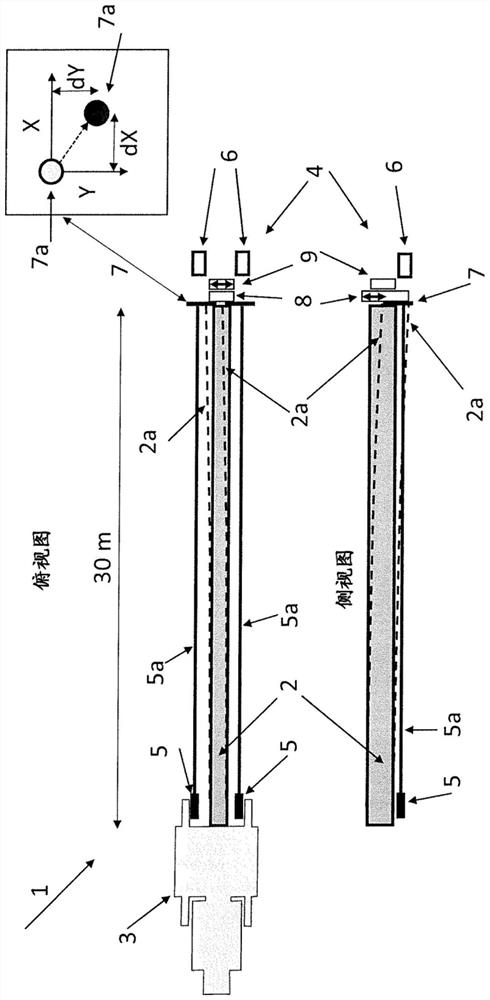
[0028] In the device 1 shown, the boom 2 is fastened to a suspension 3 . The tubes or profiles to be welded are not shown as they are not necessary for understanding the invention. However, it is conceivable that the device 1 is located in the middle of a pipe or profile. The deflection of the cantilever 2 due to magnetic or temperature effects is shown by dashed line 2a. The top view is along the horizontal direction, and the side view is along the vertical direction. A welding head 4 is mounted on the end of the boom 2 , movable vertically and horizontally perpendicular to the axis of the boom 3 , wherein the welding head 4 itself is not shown. Two lasers 5 are fixed on the suspension 3 . Each laser beam 5 a is aimed at two cameras 6 fixed on the ends of the cantilever 3 . A transparent, preferably white-coloured plate 7 is arranged in the beam path between the laser 5 and the camera 6 , wherein there can be a pair of cameras for each laser and naturally also a plate 7 i...


PUM


Abstract

The invention relates to a device (1) for internal welding of pipes and profiles, comprising a cantilever (2, 2a) which is fastened to a suspension (3) and which can be introduced into a pipe or profile to be welded and on which a welding head (4) is movably mounted, the cantilever (2, 2a) further comprising at least one laser (5) and at least one camera (6). In order to reduce the adverse effects of magnets and heat on the position of the welding head (4), it is proposed according to the invention that a laser (5) is mounted on the suspension (3) and a camera (6) is mounted on the end of the boom (3) or on the welding head (4) in order to observe the laser beam (5a). A correction signal is calculated from a change in the position of the laser beam (5a) observed by means of the camera (6) and is continuously conducted to a control unit in order to guide the welding head (4) by means of the displacement means (8, 9).

Description

technical field [0001] The invention relates to a device and a method for the internal welding of pipes and profiles, the device comprising a cantilever on which the cantilever is fixed, the cantilever can be introduced into the pipe or profile to be welded and the welding head is movably mounted on on the cantilever, wherein the cantilever also includes a laser and a camera. Background technique [0002] During internal welding, the welding head is usually placed on the end of a long cantilever which is driven into the pipe or profile. The media required for welding (gas, welding current, welding cables, flux, welding wire, . . . ) are guided to the welding head via or along the cantilever. [0003] Such devices and methods are known, for example, from US 3,764,056 and US 10,040,141 B2. [0004] Document US 3,764,056 discloses a device by means of which pipes can be welded together starting from the inside of the pipes. Here, the cantilever, at whose tip the welding head...

Claims


Application Information

Patent Timeline
IPC IPC(8): B21C37/08B23K26/03B23K26/044B23K26/24B23K26/282B23K37/02B23K9/18B23K101/06
CPCB23K9/18B23K37/0276B23K37/027B23K37/0211B23K2101/06
Inventor M·斯达克
Owner SMS GRP GMBH
Why Eureka
Try Eureka