Water passing device and maintenance method thereof

A water-through and water-through hole technology, which is applied in the direction of earthwork drilling and cutting machinery, etc., can solve the problems of coal mining in violation of safety regulations, inconvenient maintenance, and inconvenient maintenance, so as to improve reliability, facilitate cleaning, improve The effect of cleanliness

Pending Publication Date: 2022-04-29
SHANGHAI TIANDI MINING EQUIP TECH CO LTD +2
View PDF0 Cites 0 Cited by
  • Summary
  • Abstract
  • Description
  • Claims
  • Application Information

AI Technical Summary

Problems solved by technology

[0003] One is easy to wear or desoldering failure: because the water passage mechanism between the drum end plate and the blades, that is, the U-shaped tube protrudes from the outer surface of the cylinder ring and adopts a welded structure, the water passage device is easy to be cut off during use. Coal and rock smashing and friction extrusion, etc., are prone to water leakage caused by wear or desoldering
[0004] The second is inconvenient maintenance: this type of water passage mechanism may be blocked during use, but after the blockage occurs, due to the welded structure, maintenance is inconvenient, and it is usually necessary to carry out major projects such as cutting the weld seam by Masui. The cost is very high, which often leads some companies with loose management to even give up maintenance, and the phenomenon of illegal coal mining in violation of safety regulations occurs from time to time

Method used


Image

  • Water passing device and maintenance method thereof
  • Water passing device and maintenance method thereof
  • Water passing device and maintenance method thereof

Examples


Embodiment Construction

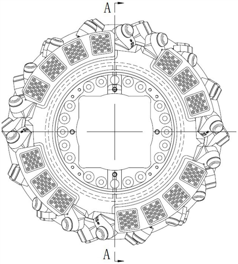
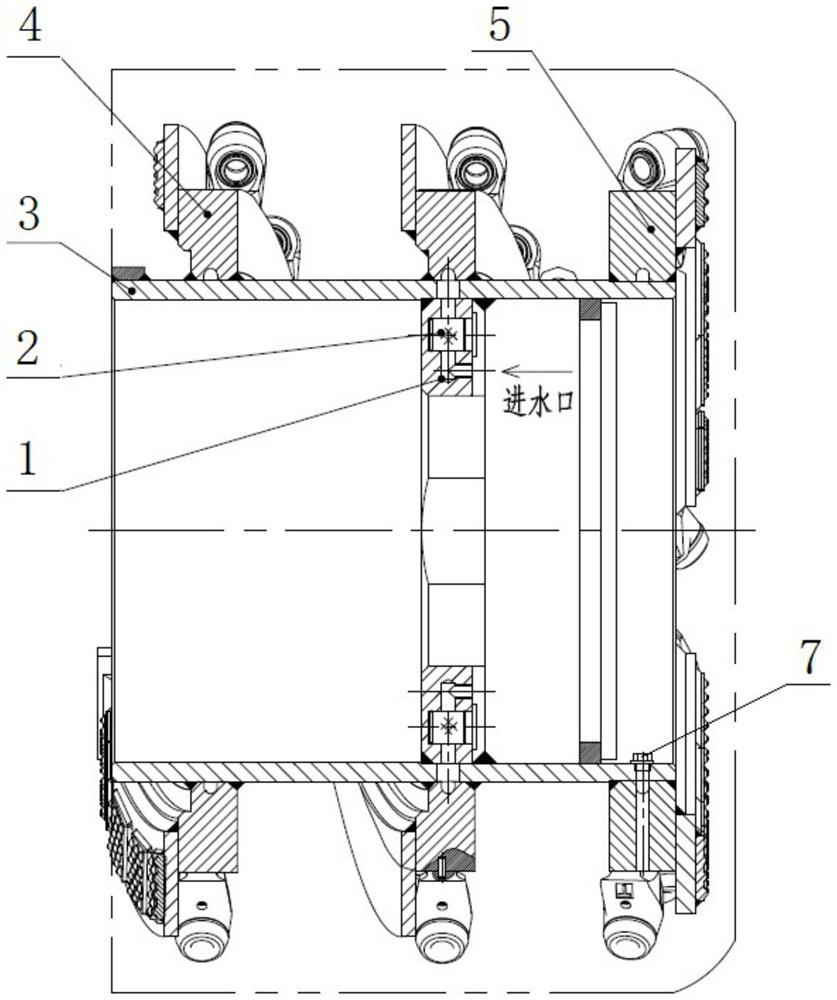
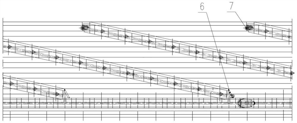
[0031] The invention discloses a water passing device, such as Figure 1-7 As shown, it includes a cylinder ring 3, a number of blades 4 spirally wound on the outer cylindrical surface of the cylinder ring and fixed by welding, and an end plate 5 welded and fixed on one end of the outer cylinder surface of the cylinder ring. A circle of water passage holes 3-1 on the end disk of the cylinder ring and a plurality of water passage holes 3-2 on the cylinder connection disk scattered in the circumferential direction are arranged on the cylinder ring along the circumferential direction. The water passage hole of the end plate of the cylinder ring is close to the end of the cylinder ring, and the axial direction corresponds to the position where the end plate is installed on the cylinder ring. The position of the water passage hole of the cylinder ring connecting plate in the axial direction corresponds to the position of the fixed connecting plate inside the cylinder ring. The rad...


PUM


Abstract

The invention relates to a water passing device and a maintenance method thereof. The water passing device comprises a cylinder ring end disc water passing hole and a cylinder ring connecting disc water passing hole which are formed in the cylinder ring, an end disc water passing groove, an end disc connecting water passing groove and an end disc water passing hole which are formed in the end disc, and blade water passing grooves and blade water passing holes which are formed in the blades. The water inlet channel is formed in the connecting disc, the triangular water tank is arranged at the joint of the end disc and the starting end of the blade, the water inlet channel, the cylinder ring connecting disc water through hole, the blade water through groove and the blade water through hole are sequentially communicated, and the cylinder ring end disc water through hole, the end disc connecting water through groove, the end disc water through groove and the end disc water through hole are communicated. The triangular water tank is communicated with the blade water through tank and the end disc connecting water through tank at the same time; the maintenance method of the water supply device comprises the step of respectively inserting flexible steel bars into the water channels in the end disc and the blades to clean the corresponding water channels. Abrasion and sealing-off failure in use can be avoided, maintenance is easy, the service life of the roller can be prolonged, and the safety of the underground working environment is improved.

Description

technical field [0001] The invention relates to a water passing device for spraying inside a coal shearer drum and a maintenance method thereof. Background technique [0002] Article 119 (2) of the "Coal Mine Safety Regulations" stipulates that the working pressure of the spray device in the shearer shall not be less than 2MPa. The spray in the shearer is realized by the drum, so the drum is equipped with a water device. At present, the water channel in the end plate and the water channel in the blade of the commonly used water passage device are connected by a U-shaped tube, and its use has the following problems: [0003] One is easy to wear or desoldering failure: because the water passage mechanism between the drum end plate and the blades, that is, the U-shaped tube protrudes from the outer surface of the cylinder ring and adopts a welded structure, the water passage device is easy to be cut off during use. Coal and rock smashing and friction extrusion, etc., are pron...

Claims


Application Information

Patent Timeline
Patent Type & Authority Applications(China)
IPC IPC(8): E21C35/00
CPCE21C35/00
Inventor 黄秋来李辉马子尧恩建峰陶嵘曹杨朱红徐文锋郭岱
Owner SHANGHAI TIANDI MINING EQUIP TECH CO LTD
Why Eureka
Try Eureka