Nuclear waste gas all-oxidation combustion treatment device

A treatment device and waste gas technology, applied in the direction of gas fuel burners, burners, combustion types, etc., can solve the conditions that the tail gas does not have direct discharge, cannot realize the precise control of the flame temperature and waste gas residence time, and cannot adapt to nuclear waste gas Incineration requirements and other issues to achieve the effect of improving treatment efficiency and prolonging burning time

Pending Publication Date: 2022-04-29
BEIJING SHENKEBOSI THERMAL ENERGY ENG TECH CO LTD
View PDF0 Cites 0 Cited by
  • Summary
  • Abstract
  • Description
  • Claims
  • Application Information

AI Technical Summary

Problems solved by technology

When the above combustion conditions cannot be guaranteed, the tail gas after burning nuclear waste gas does not meet the conditions for direct discharge
[0003] At present, in the field of industrial tail gas incineration at home and abroad, traditional combustion methods such as industrial torches and incinerators are often used. The tail gas treated is also mainly non-radioactive-containing tail gas such as non-ferrous metal smelting and chemical plant tail gas. Customized burner design for nuclear exhaust of radioactive materials
At the same time, the above-mentioned traditional waste gas incineration methods are all extensive combustion, which cannot achieve precise control of flame temperature and waste gas residence time, and cannot meet the incineration requirements of nuclear waste gas
[0004] In view of the related technologies mentioned above, the inventor believes that traditional industrial tail gas treatment equipment cannot meet the requirements for nuclear waste gas treatment

Method used


Image

  • Nuclear waste gas all-oxidation combustion treatment device
  • Nuclear waste gas all-oxidation combustion treatment device
  • Nuclear waste gas all-oxidation combustion treatment device

Examples


Embodiment 1

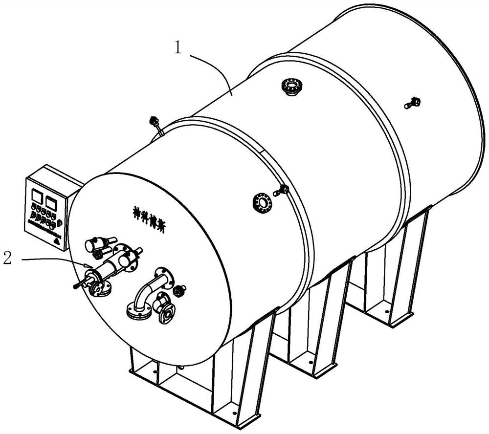
[0035] Embodiment 1: A nuclear waste gas total oxidation combustion treatment device, such as figure 1 As shown, it includes an incinerator 1 and an ultra-low nitrogen strong swirl high-speed burner 2 installed at one end of the incinerator 1 .

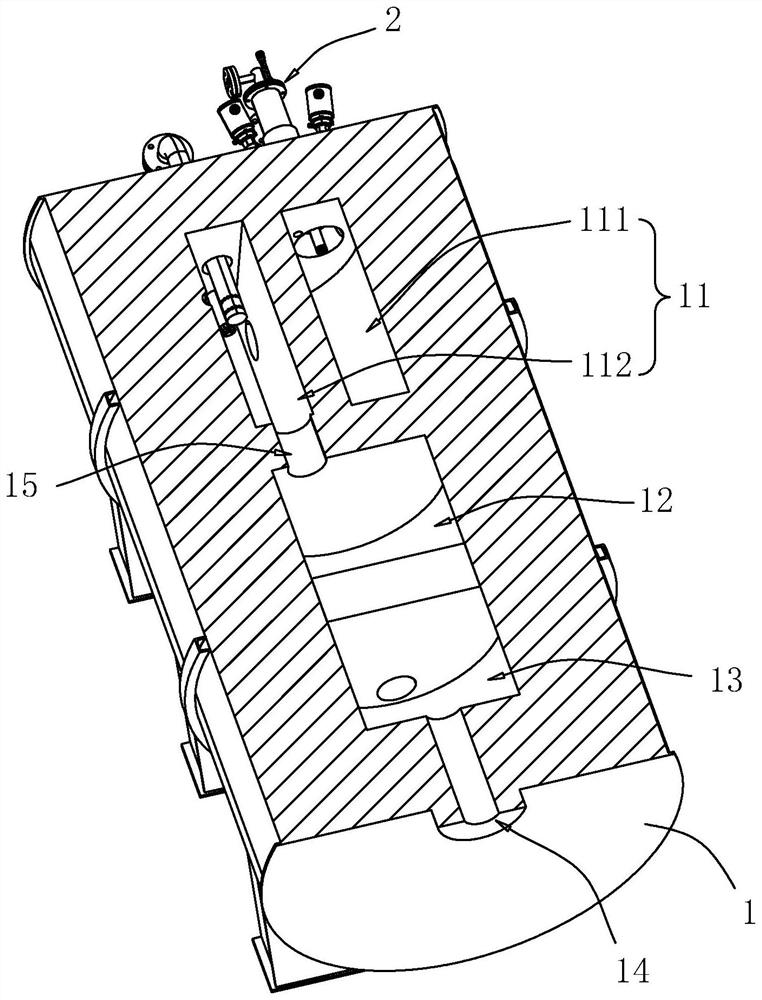
[0036] Such as figure 2 As shown, the incinerator 1 includes a front-stage combustion chamber 11, a middle-stage combustion chamber 12, and a final-stage combustion chamber 13, which are located on one side of the ultra-low nitrogen strong swirl high-speed burner 2 and are distributed sequentially toward the other end of the incinerator 1. The outer wall of the incinerator 1 There is also an exhaust port 14 communicating with the final combustion chamber 13 on the top. Wherein, the front combustion chamber 11 includes a primary flame combustion chamber 111 and a secondary mixing combustion chamber 112 . The primary flame combustion chamber 111 , the secondary mixing combustion chamber 112 , the middle combustion chamber 12 , and th...


PUM


Abstract

The invention relates to the field of nuclear waste gas treatment equipment, in particular to a nuclear waste gas full-oxidation combustion treatment device which comprises an incinerator, a front-section combustion chamber, a middle-section combustion chamber and a tail-section combustion chamber which are used for prolonging the flowing time of waste gas in the incinerator are arranged in the incinerator, and the front-section combustion chamber, the middle-section combustion chamber and the tail-section combustion chamber are sequentially communicated; the incinerator is further provided with an ultra-low-nitrogen strong-rotational-flow high-speed burner communicated with the front-section combustion chamber. The ultra-low nitrogen strong rotational flow high-speed burner comprises a waste gas pipe for introducing nuclear waste gas and water vapor at the same time; the exhaust gas pipe is sleeved with the air pipe, and the air pipe is used for introducing combustion-supporting air which cools the exhaust gas pipe and assists the ultra-low nitrogen strong rotational flow high-speed burner in supporting combustion; the fuel gas pipe is arranged outside the waste gas pipe in a sleeving manner and used for introducing fuel gas mixed with the combustion-supporting air, and the igniter is used for igniting a mixture of the combustion-supporting air and the fuel gas. Harmless incineration treatment of the nuclear waste gas is achieved.

Description

technical field [0001] The present application relates to the field of nuclear waste gas combustion, in particular to a nuclear waste gas total oxidation combustion treatment device. Background technique [0002] In the field of nuclear physics applications, a large amount of nuclear waste gas containing radioactive substances is often produced after the completion of the main process. Due to its complex composition, flammability and certain radioactive substances, the nuclear waste gas has become one of the important technical problems in the field of nuclear applications at home and abroad. . At present, the treatment method of nuclear waste gas is mainly based on combustion, but in order to ensure that the exhaust gas after burning nuclear waste gas is harmless, it is necessary to control the flame temperature of the combustion process and the residence time of nuclear waste gas at high temperature, which is an urgent need in the industry. One of the practical problems t...

Claims


Application Information

Patent Timeline
Patent Type & Authority Applications(China)
IPC IPC(8): F23G7/06F23G5/16F23G5/44F23G5/50F23D14/02F23D14/46F23D14/64
CPCF23G7/06F23G5/16F23G5/44F23G5/50F23D14/02F23D14/64F23D14/46
Inventor 王鸿川
Owner BEIJING SHENKEBOSI THERMAL ENERGY ENG TECH CO LTD
Why Eureka
Try Eureka