Thermal floating type inverter

An inverter, floating technology, applied in the field of thermal floating inverter, can solve the problem of increasing the gap of the heat dissipation hole, and achieve the effect of increasing the gap, improving the heat dissipation efficiency, and reducing the aggregation

Pending Publication Date: 2022-04-29
武玉彦
View PDF0 Cites 0 Cited by
  • Summary
  • Abstract
  • Description
  • Claims
  • Application Information

AI Technical Summary

Problems solved by technology

[0005] Aiming at the problems existing in the prior art, the purpose of the present invention is to provide a thermal floating inverter, through the setting of the floating bar, with the accumulation of heat, the floating bar is gradually heated, so that it is gradually separated from the inner stay, Gradually lift from the middle to both sides, on the one hand, effectively increase the gap of the heat dissipation holes, accelerate the overflow of heat accumulated inside, and greatly improve the heat dissipation efficiency; The warning function enables the user to perform manual intervention in time to reduce the accumulation of internal heat and reduce the probability of failure. In addition, as the accumulation time prolongs, the lifting angle of the floating bar gradually increases. At this time, multiple heat on it The reflection ball gradually gathers, which further plays an early warning role for the user, and is convenient for the user to judge the heat accumulation in the inverter body

Method used


Image

  • Thermal floating type inverter
  • Thermal floating type inverter
  • Thermal floating type inverter

Examples


Embodiment 1

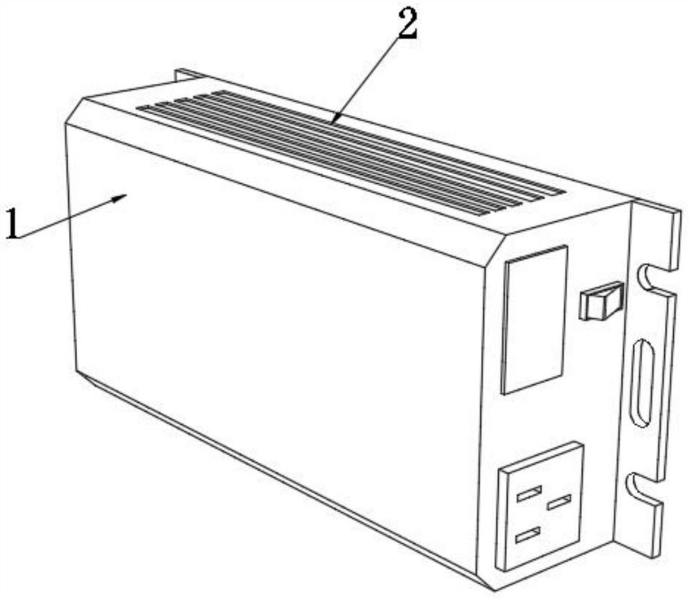
[0037] see figure 1 , a thermal floating inverter, including an inverter body 1, a plurality of evenly distributed heat dissipation holes 2 are arranged on the outer shell of the inverter body 1, and inner stays 3 are fixedly connected to the inner walls of the heat dissipation holes 2, where It should be noted that when in use, the inner stays 3 are only installed in the cooling holes 2 on the upper side.

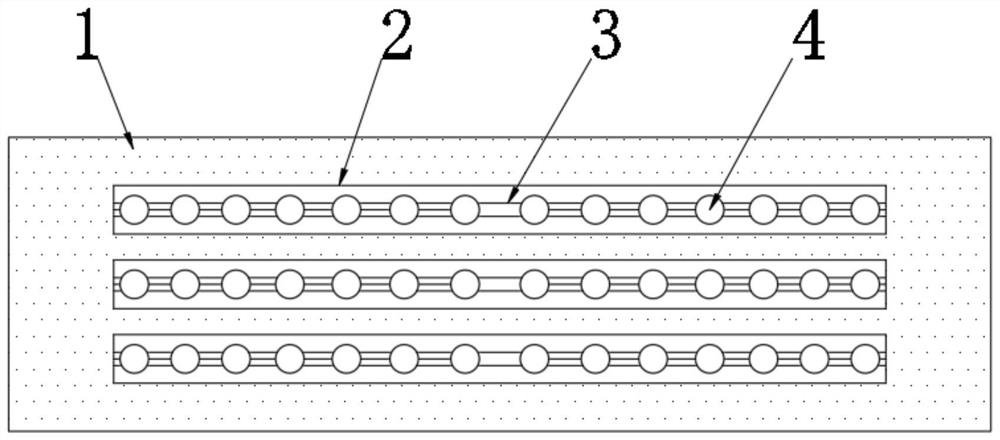
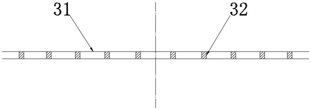
[0038] see Figure 2-4 , the inner stay 3 includes two side wires 31 on the same horizontal plane and a plurality of positioning pieces 32 connected between the two side wires 31, and the inner wall of the cooling hole 2 is also fixedly connected with two mutually symmetrical floating bars 4, as Figure 5 The floating bar 4 includes a plurality of heat-reflecting balls 41 and a series bar 42 connected between two adjacent heat-reflecting balls 41, and the heat-reflecting balls 41 near the left and right inner walls of the heat dissipation hole 2 are also connected with th...

Embodiment 2

[0044] see Figure 9-10 , the position corresponding to the series bar 42 in the active floating end 411 is fixedly connected with the air shield 71, and the limit rope 72 is fixedly connected between the end of the air shield 71 and the inner wall of the active floating end 411. Since the active floating end 411 expands and deforms when heated, The limit rope 72 can effectively limit the position of the air shield 71, making it difficult to change its orientation with its deformation, thereby effectively ensuring that the thermal reflection ball 41 can move smoothly along the series bar 42. One end of the series bar 42 moves through the active floating end 411 and Extending into the air shield 71, the other end of the series bar 42 is fixedly connected to another active floating end 411 adjacent to it, and the series bar 42 is a T-shaped hard structure, and the air shield 71 is a hard sealing structure, which is convenient for the floating bar 4 After the lifting angle is inc...


PUM


Abstract

The invention discloses a thermal floating type inverter, and belongs to the field of inverters, according to the thermal floating type inverter, floating strips are gradually heated along with heat accumulation, so that the floating strips are gradually separated from inner supporting strips and gradually lifted from the middle to the two sides, on one hand, gaps of heat dissipation holes are effectively enlarged, overflow of heat accumulated inside is accelerated, and the heat dissipation efficiency is improved; on the other hand, after the floating strip is lifted outwards, an obvious warning effect can be achieved on a user, the user can conduct manual intervention in time, accumulation of internal heat is reduced, the fault occurrence probability is reduced, in addition, along with prolonging of the accumulation time, the lifting angle of the floating strip is gradually increased, and the heat dissipation efficiency is greatly improved. And at the moment, the plurality of heat reflecting balls on the inverter body gradually gather, so that an early warning effect is further achieved for a user, and the user can conveniently judge the heat gathering condition in the inverter body.

Description

technical field [0001] The invention relates to the field of inverters, more specifically, to a thermal floating inverter. Background technique [0002] The inverter is a converter that converts DC power (battery, storage battery) into constant frequency and constant voltage or frequency modulation and voltage modulation AC (generally 220V, 50Hz sine wave). It consists of inverter bridge, control logic and filter circuit. The inverter is a DC to AC transformer, which is actually a process of voltage inversion with the converter. The converter converts the AC voltage of the grid into a stable 12V DC output, while the inverter converts the 12V DC voltage output by the Adapter into a high-frequency high-voltage AC. [0003] After the inverter is used for a long time, or connected to the electrical equipment that is difficult to carry, it will generate a lot of heat after a certain period of time. In the prior art, cooling holes are generally used to dissipate heat. However, w...

Claims


Application Information

Patent Timeline
Patent Type & Authority Applications(China)
IPC IPC(8): H02M7/00H05K7/20G01K1/02
CPCH02M7/003H05K7/2089G01K1/02
Inventor 武玉彦
Owner 武玉彦
Why Eureka
Try Eureka